Magnetic circuit and speaker

a magnetic circuit and speaker technology, applied in the direction of transducer details, other angling devices, multi-purpose tools, etc., can solve the problems of inefficiency of effective magnetic flux, inability to efficiently take out magnetic energy (effective magnetic flux) of magnets b>1/b>, b>1/b>, b>1/b>, etc., and achieve the effect of improving the frequency characteristi

Inactive Publication Date: 2008-01-08
SONY CORP
View PDF1 Cites 19 Cited by
  • Summary
  • Abstract
  • Description
  • Claims
  • Application Information

AI Technical Summary

Benefits of technology

[0024]According to a speaker of the third aspect of the present invention, a voice coil wound around a voice coil bobbin is arranged to oppose the second magnet of the second layer inside a ring-shaped or polygonal frame-shaped magnetic circuit including three layers and the approximately the same vibration system which is composed of a diaphragm and an edge are connected to both the ends of a voice coil bobbin, so that a speaker which has the vibration system symmetrical with respect to a center axis perpendicular to the direction of a center axis of the voice coil can be obtained.
[0025]According to a speaker of the fourth aspect of the present invention, the winding direction of the voice coil wound around a bobbin to oppose the second magnet of the second layer is the reverse direction to the winding direction of voice coils wound around a bobbin to oppose to the first magnet of the first layer and third magnet of the third layer to be connected in series, so that a speaker which has a small inductance component of the input impedance can be obtained. Further, since a voice coil is formed with the winding directions of the first and third voice coils opposite, the direction of a driving force from the second magnet of the second layer which the voice coil opposes, and the direction of a driving force from the first and third voice coils which oppose the first and third magnets of the first and third layers in which the magnetic flux has an opposite direction to the second magnet of the second layer become the same direction, so that a sufficient driving force can be obtained though the speaker is thin and light in weight.
[0026]In the present invention, since the polarities of the three sheets of magnets are used to form a magnetic circuit, a speaker and magnetic circuit which are extremely thin and light in weight can be obtained.
[0027]Further, since a voice coil is wound approximately in the center of the outer circumference of a voice coil bobbin and a symmetrical vibration system is connected to both the ends of this voice coil, a speaker and magnetic circuit of high sound quality can be obtained.
[0028]Furthermore, the first, second and third coils are wound around a voice coil bobbin at the positions which oppose respective magnets, and the winding direction of the first and third coils wound at the positions opposing the first and third magnets of the first layer and third layer is reverse to the winding direction of the second coil wound at the position opposing the second magnet of the second layer to form a voice coil, and therefore the second coil obtains a driving force from the second magnet of the second layer, and the first and third coils obtain a driving force from the portion around the first and third magnets of the first and third layers where the magnetic field of the reverse direction occurs, so that a magnetic circuit and a speaker of light-weight and thin-shaped, nevertheless, with a sufficient driving force can be obtained.
[0029]Moreover, the inductance component of the input impedance of a speaker is made to decrease, the high frequency characteristic is improved, and a ferromagnetic substance which has the magnetic flux density saturation characteristic is not used as a part of the magnetic circuit, so that a magnetic circuit and speaker can be obtained in which the saturation phenomenon of the magnetic flux density does not occur even if a magnet having a considerably large magnetic energy is used.

Problems solved by technology

However, in a frame-shaped or ring-shaped magnetic circuit, magnetic flux converges in the outer circumference of a frame-shaped or ring-shaped magnetic circuit, and this magnetic flux becomes useless because it does not contribute at all to drive a speaker.
Further, in such magnetic circuit, when using a spacer 6 made of non-magnetic material, the magnetic energy (effective magnetic flux) which the magnets 1, 1a and 1b have can not be taken out efficiently.
Furthermore, though the magnetic energy can be taken out efficiently when using a spacer 6 made of a ferromagnetic material, the magnetic flux density of the spacer 6 made of a ferromagnetic material is saturated when a magnet having a large magnetic energy is used, resulting in difficulty in which an effective magnetic flux cannot be taken out efficiently.

Method used


Image

  • Magnetic circuit and speaker
  • Magnetic circuit and speaker
  • Magnetic circuit and speaker

Examples


embodiment 1

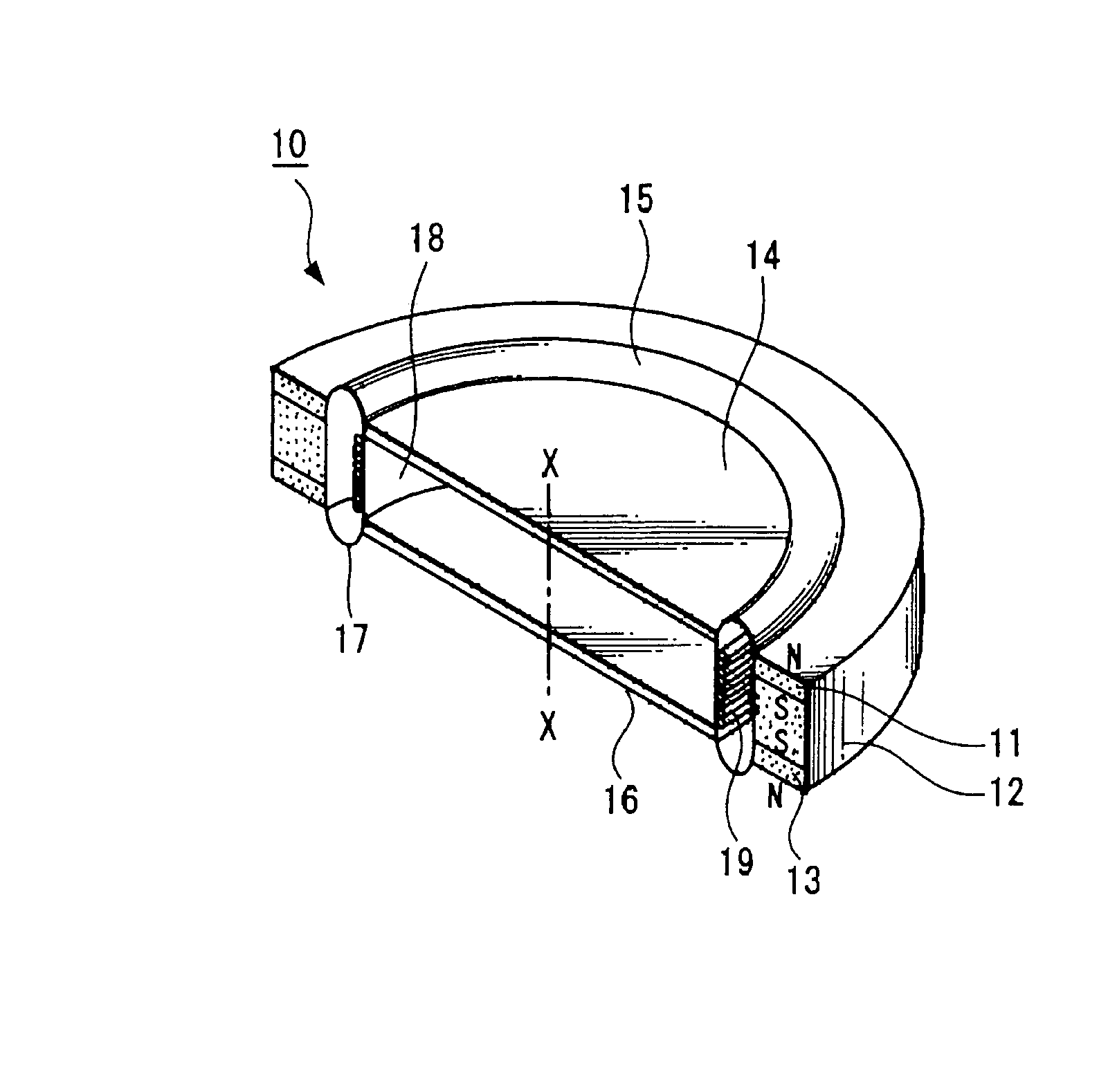
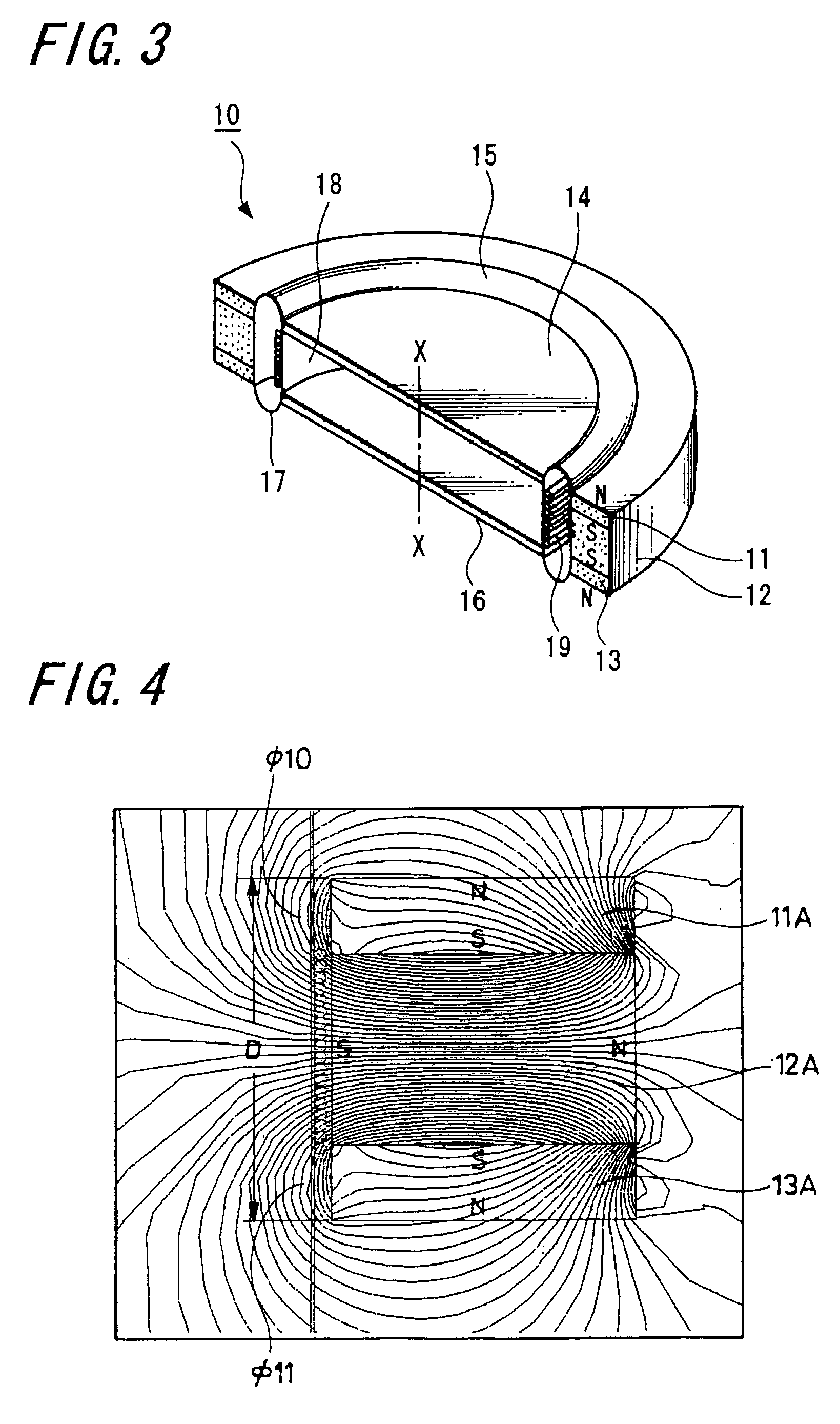
[0039]An embodiment of the present invention is hereinafter explained based on the drawings. FIG. 3 is a perspective and partly sectional view of a speaker showing an embodiment of a speaker which has a symmetrical vibration system in the vibration direction, using a magnetic circuit of the three layered magnetic structure of the present invention. In FIG. 3, a numeral 10 denotes the whole of a speaker, which shows an example using a magnetic circuit, including magnets in the shape of a ring, which is symmetrical with respect to a center axis X-X of a voice coil 19 constituting the magnetic circuit. The first ring-shaped magnet 11 of the first layer and the third ring-shaped magnet 13 of the third layer are arranged in the directions to repel each other and are magnetized in the direction of thickness of the first magnet and third magnet such as N, S (S, N) and S, N (N, S). The second magnet 12 of the second layer is formed to be a ring-shaped magnet thicker than the first and third...

embodiment 2

[0056]FIG. 6 is a vertically sectional view showing a magnet circuit and speaker of another embodiment of the three layered magnet structure according to the present invention. In the embodiment shown in FIG. 6 a magnetic circuit in the shape of a ring that is symmetrical with respect to a center axis X-X is used. A first magnet 11C of the first layer and a third magnet 13C of the third layer are magnetized in the directions which repel each other and are magnetized in the direction of the thickness thereof. A second magnet 12C of the second layer is magnetized in the direction perpendicular to the magnetized direction of the first magnet 11C of the first layer and third magnet 13C of the third layer arranged at the top and bottom thereof.

[0057]Further, as shown in FIG. 6, the polarity on the side of the inner diameter of the second magnet 12C of the second layer is magnetized to become opposite to that of the upper surface of the first magnet 11C of the first layer and the bottom s...


PUM


Abstract

A speaker and a magnetic circuit for a speaker, in which the high quality sound is obtained, are provided using a structure which is thin, light-weight and symmetrical in the vibration direction. In three sheets of layered magnets, the first magnet of the first layer and the third magnet of the third layer are arranged in the magnetic directions which repel each other, and the polarity of second magnet of the second layer is arranged perpendicularly to the polarity of the first and third magnets of the first and third layers at the top and bottom thereof. A voice coil wound near the center of a voice coil bobbin is arranged to oppose the second magnet of the second layer of the magnetic circuit composed of the three layers, and the same vibration systems composed of the diaphragms and edges are connected to both the ends of this voice coil bobbin. Accordingly, the speaker which has a vibration system that is symmetrical with respect to a center axis X-X perpendicular to the direction of a center axis of a voice coil is obtained.

Description

BACKGROUND OF THE INVENTION[0001]1. Field of the Invention[0002]The present invention relates to a magnetic circuit and a speaker and particularly relates to a magnetic circuit which includes only a magnet without a yoke, which is thin and light in weight and which has a symmetrical structure with respect to the vibration direction, and to the improvement of a speaker using this magnetic circuit.[0003]2. Description of the Related Art[0004]Conventionally, as a thin type speaker or magnetic circuit for a speaker, it is known one disclosed in patent literature 1 in which thin disk-shaped or ring-shaped two sheets of magnets with the same polarity of S, S (N, N) are arranged opposing each other with a spacer made of a non-magnetic material positioned in between.[0005]FIG. 1 shows a vertically sectional view of a speaker disclosed in Japan Published Utility Model Application No. H2-30957, in which the magnetic circuit includes: first and second ring-shaped magnets 1 and 1 magnetized in ...

Claims


Application Information

Patent Timeline
Patent Type & Authority Patents(United States)
IPC IPC(8): H04R1/02H04R11/02H04R9/00H04R9/02H04R9/04H04R9/06
CPCH04R9/025H04R9/06A01K97/06Y10S81/01
Inventor OHASHI, YOSHIO
Owner SONY CORP
Why Eureka
Try Eureka