Telemetry antenna for an implantable medical device

a technology of telemetry antenna and medical device, which is applied in the direction of individually energised antenna array, protective material radiating elements, therapy, etc., can solve the problems of limiting the data transfer distance between the programmer head and the imd rf telemetry antenna to a few inches, and attenuating the radiated rf field

Active Publication Date: 2008-01-08
MEDTRONIC INC
View PDF3 Cites 115 Cited by
  • Summary
  • Abstract
  • Description
  • Claims
  • Application Information

AI Technical Summary

Problems solved by technology

As the technology has advanced, IMDs have become ever more complex in possible programmable operating modes, menus of available operating parameters, and capabilities of monitoring increasing varieties of physiologic conditions and electrical signals which place ever increasing demands on the programming system.
Generally, the antenna is disposed within the hermitically sealed housing; however, the typically conductive housing adversely attenuates the radiated RF field and limits the data transfer distance between the programmer head and the IMD RF telemetry antennas to a few inches.
These approaches are generally undesirable in that depending upon the option selected they require substantial modification of the housing and / or heading, require additional components added to the housing (e.g., dielectric shrouds about a portion of the housing), reduce the effectiveness of other components (e.g., reducing the surface area available for use as a can electrode), create a directional requirement (e.g., require that the IMD be oriented in a particular direction during implant for telemetry effectiveness), or finally that they add extraneous exposed components that are subject to harmful interaction in the biological environment or require additional considerations during implant (e.g., stub antennas extending outward from the device).

Method used


Image

  • Telemetry antenna for an implantable medical device
  • Telemetry antenna for an implantable medical device
  • Telemetry antenna for an implantable medical device

Examples


Embodiment Construction

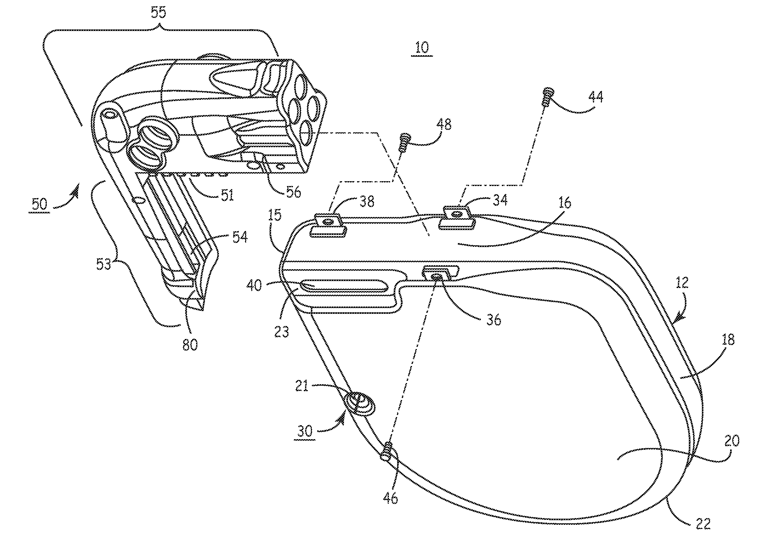
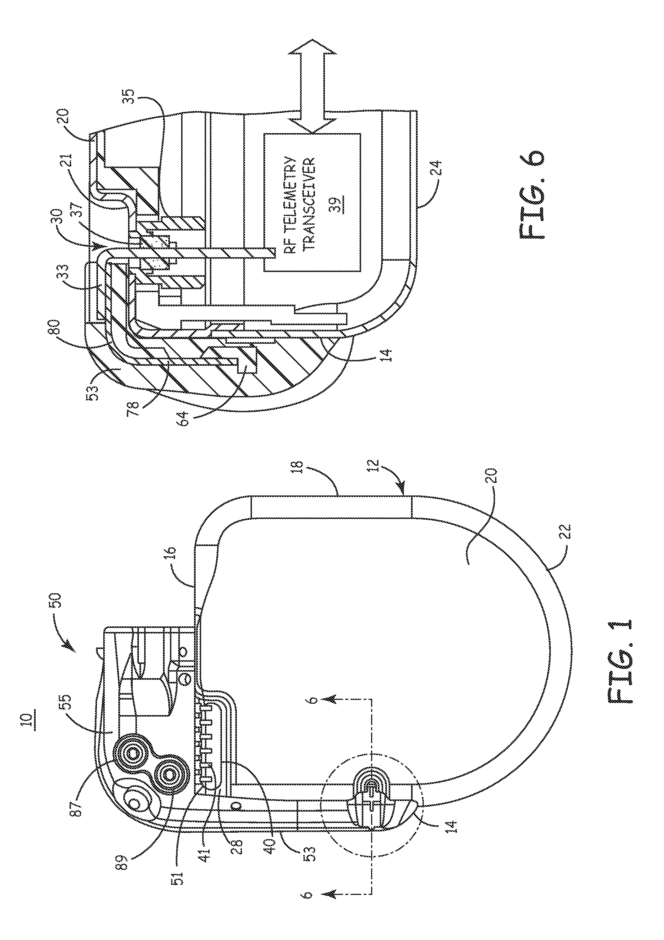
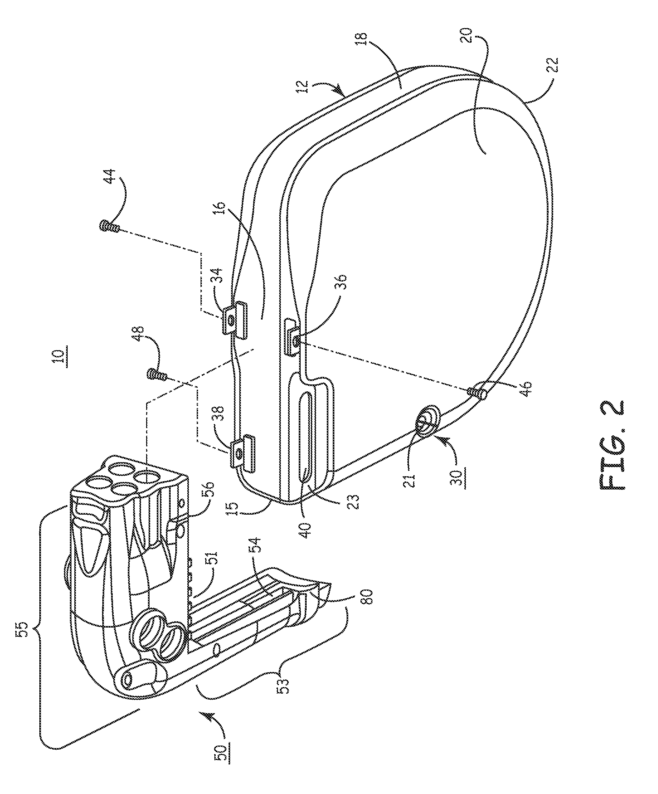
[0029]The present invention relates to providing an improved RF telemetry antenna disposed outside a hermetically sealed housing of an IMD. The following description provides various embodiments in the context of an ICD. However, the present invention is intended to be implemented with a wide variety of IMD's.

[0030]The IMD telemetry antenna has two primary functions: to convert the electromagnetic power of a DT transmission of an EMD telemetry antenna propagated through the atmosphere and then through body tissues into a UHF signal that can be processed by the IMD transceiver into commands and data that are intelligible to the IMD electronic operating system; and to convert the UT UHF signals of the IMD transceiver electronics into electromagnetic power propagated through the body tissue and the atmosphere so that the EMD can receive it.

[0031]In the embodiment illustrated in FIG. 1, a first IMD telemetry antenna element is supported to extend in a first direction along a first minor...


PUM


Abstract

A telemetry antenna for an implantable medical device includes one or more portions having a non-linear configuration. In some embodiments, the non-linear configuration provides an antenna having a greater antenna length than the linear lengthwise dimension of the antenna structure. In some embodiments, the non-linear configuration is a serpentine pattern.

Description

FIELD OF THE INVENTION[0001]The present invention relates generally to a telemetry antenna and methods of fabrication for an implantable medical device (IMD) including a telemetry antenna.BACKGROUND OF THE INVENTION[0002]A variety of implantable medical devices (IMD's) exist that provide diagnostic or therapeutic capabilities. These IMD's include, for example, cardiac pacemakers, implantable cardioverters / defibrillators (ICD's), and various tissue, organ and nerve stimulators or sensors. IMD's typically include their components within a hermetically sealed enclosure referred to as a “can” or housing. In some IMD's, a connector header or connector block is attached to the housing and allows interconnection with one or more elongated electrical medical leads.[0003]The header is typically molded from of a relatively hard, dielectric, non-conductive polymer having a thickness approximating the housing thickness. The header includes a mounting surface that conforms to and is mechanically...

Claims


Application Information

Patent Timeline
Patent Type & Authority Patents(United States)
IPC IPC(8): A61N1/08A61N1/372
CPCA61N1/37229H01Q1/273H01Q1/36Y10S128/903
Inventor TWETAN, LEN D.PRZYBYSZEWSKI, PIOTRDUBLIN, GARRY L.HAUBRICH, GREGORY J.HOUGHAM, ANDRINA J.RIES, ANDREW J.ENGMARK, DAVID B.GROSE, GARY M.
Owner MEDTRONIC INC
Why Eureka
Try Eureka