Angular rate sensor and mounting structure of angular rate sensor

a technology of angular rate sensor and mounting structure, which is applied in the direction of acceleration measurement using interia force, turn-sensitive devices, instruments, etc., can solve the problems of small amount of vibration produced by drive-purpose vibrators with respect, detection output error, and adverse influences caused by the upper and lower vibrations of vehicles, etc., to achieve stable driving vibration of vibrators.

Inactive Publication Date: 2008-01-15
DENSO CORP
View PDF5 Cites 16 Cited by
  • Summary
  • Abstract
  • Description
  • Claims
  • Application Information

AI Technical Summary

Benefits of technology

[0020]In the above sensor, bending amount of the angular velocity detection-purpose vibrator in the second direction caused by driving vibration of the drive-purpose vibrator becomes sufficiently small. Thus, output error in the sensor is reduced so that detection accuracy of the sensor is improved.
[0023]In the sensor, the vibrating direction of the vibrator is perpendicular to a gravitational direction. Thus, the gravity does not affect the driving vibration of the vibrator substantially. Thus, the driving vibration of the vibrator is stable as much as possible.

Problems solved by technology

However, since the angular velocity detection-purpose vibrator has been manufactured in such a shape which is elongated along the second direction, only a very small amount of the vibrations produced from the drive-purpose vibrator is transferred with respect to this angular velocity detection-purpose vibrator.
As a result, the unwanted angular velocity components may cause a detection output error.
As a result, in the angular rate sensor, there are some risks that adverse influences caused by the upper and lower vibrations of the vehicle and the gravitational acceleration may be given with respect to the driving vibrations depending upon the direction of the driving vibrations of the vibrators.
However, a leakage of vibrations may occur in response to a change in conditions of the driving vibrations, and / or electric anomalies, caused by the driving vibrations being superimposed upon detection signals, so that precision of sensor output signals may be deteriorated.

Method used


Image

  • Angular rate sensor and mounting structure of angular rate sensor
  • Angular rate sensor and mounting structure of angular rate sensor
  • Angular rate sensor and mounting structure of angular rate sensor

Examples


first embodiment

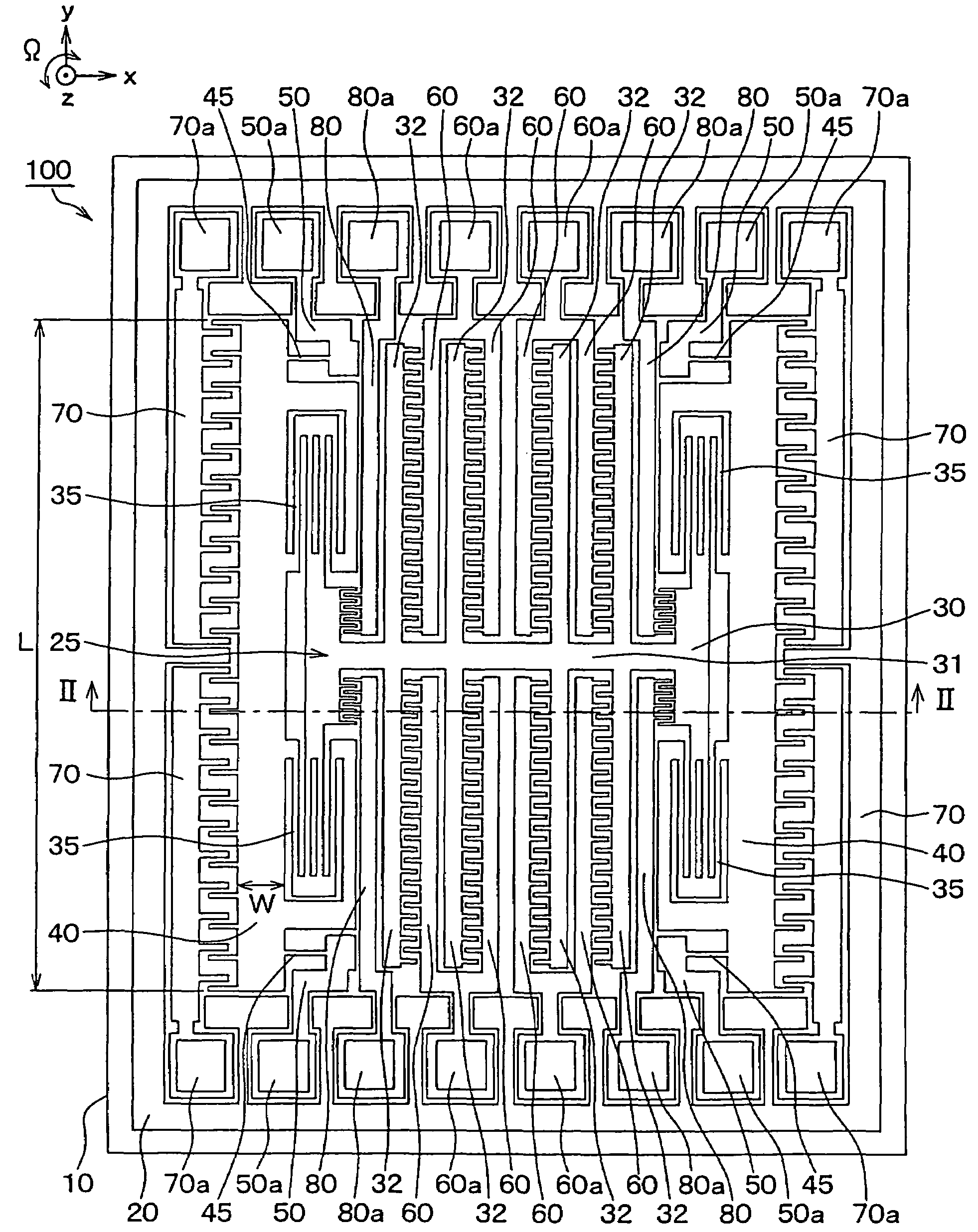
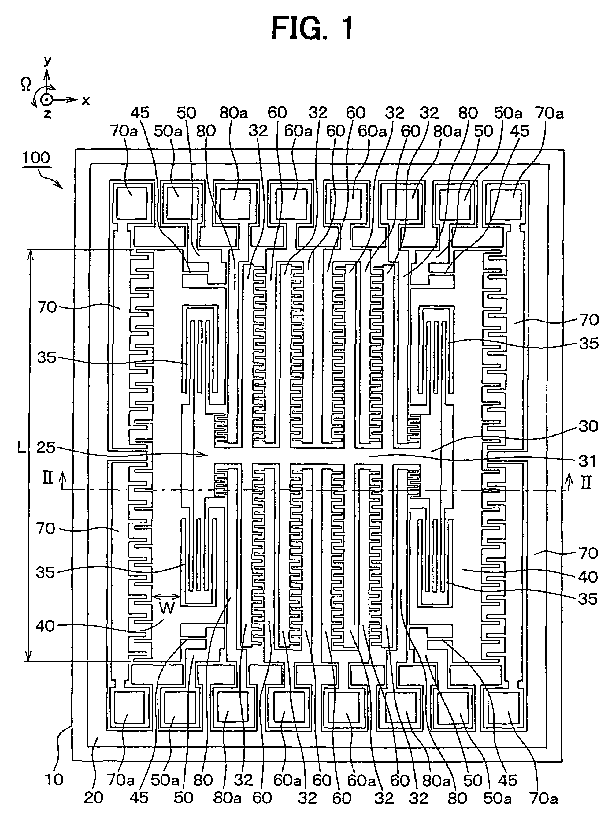
[0034]The Inventors of the present invention experimentally manufactured and investigated angular rate sensors with respect to a related art. FIG. 4 is a diagram for schematically showing a plane structure of an angular rate sensor as a trial product thereof.

[0035]This angular rate sensor is made of a semiconductor substrate 10 such as a silicon substrate. Since trenches have been formed in this semiconductor substrate 10 by employing the well-known semiconductor manufacturing technique such as an etching process, as indicated in FIG. 4, a movable electrode 25 and respective electrodes 60, 70, 80, have been segmented to be formed. The movable electrode 25 contains vibrators 30 and 40.

[0036]The movable electrode 25 has been arranged by providing a drive-purpose vibrator 30, an angular velocity detection-purpose vibrator 40, a drive beam 35 for coupling both the vibrators 30 and 40 to each other, and a detection beam 45 for coupling the angular velocity detection-purpose vibrator 40 t...

second embodiment

[0105]The inventors have preliminary studied about an angular rate sensor mounted in such a way that a detection axis corresponding to a rotation axis of an angular velocity is directed to an upper and lower direction of a vehicle, namely the vertical direction. FIG. 8 is a diagram for schematically representing a mounting condition of such an angular rate sensor 500. It should be understood that a base member is omitted in FIG. 8.

[0106]While two pieces of vibrators 520 have been provided in this angular rate sensor 500, each of the vibrators 520 is driven to be vibrated along an “x” direction corresponding to a first direction, and further, when an angular velocity “Ω” is applied, each of the vibrators 520 is vibrated so as to detect the applied angular velocity “Ω” along a “y” direction corresponding to a second direction by Coriolis force.

[0107]In this case, an “x-to-y” plane corresponds to a horizontal plane, and a detection axis “z” of the angular velocity “Ω” corresponds to th...


PUM


Abstract

An angular rate sensor includes: a substrate; a drive-purpose vibrator capable of vibrating in a first direction; and an angular velocity detection-purpose vibrator capable of vibrating in a second direction. The sensor detects an angular velocity on the basis of vibration of the angular velocity detection-purpose vibrator in the second direction caused by a Coriolis force, when the drive-purpose vibrator is vibrated in the first direction, and the angular velocity is applied to the sensor in a third direction. The angular velocity detection-purpose vibrator has a length along with the second direction and a width along with the first direction. A ratio between the width and the length is equal to or larger than 0.1.

Description

CROSS REFERENCE TO RELATED APPLICATIONS[0001]This application is based on Japanese Patent Applications No. 2004-255716 filed on Sep. 2, 2004, and No. 2004-273419 filed on Sep. 21, 2004, the disclosures of which are incorporated herein by reference.FIELD OF THE INVENTION[0002]The present invention relates to an angular rate sensor and a mounting structure of an angular rate sensor.BACKGROUND OF THE INVENTION[0003]An angular rate sensor includes a drive-purpose vibrator capable of vibrating along a first direction and an angular velocity detection-purpose vibrator capable of vibrating along a second direction perpendicular to the first direction.[0004]Generally speaking, this sort of angular rate sensor has been constituted by employing a supporting substrate, the drive-purpose vibrator, and the angular velocity detection-purpose vibrator. The drive-purpose vibrator has been supported on this supporting substrate in such a manner that the drive-purpose vibrator can be vibrated along t...

Claims


Application Information

Patent Timeline
Patent Type & Authority Patents(United States)
IPC IPC(8): G01P9/04G01C19/56
CPCG01C19/5719
Inventor OGINO, MUTSUHITO
Owner DENSO CORP
Why Eureka
Try Eureka