
Versatile stand-mounted wide area lighting apparatus

a technology of wide area lighting and stand-mounted stands, which is applied in the direction of lighting support devices, instruments, and power sources with built-in power, can solve the problems of limiting the flexibility or effectiveness of customized lighting systems, and reducing the flexibility of lighting systems

Inactive Publication Date: 2008-01-15
LITEPANELS
View PDF119 Cites 20 Cited by
  • Summary
  • Abstract
  • Description
  • Claims
  • Application Information

AI Technical Summary

Benefits of technology

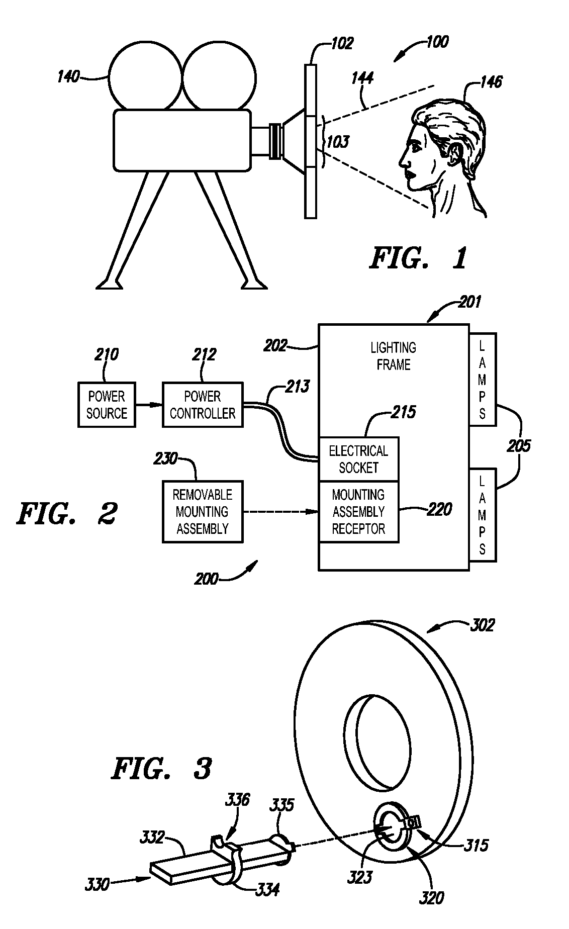
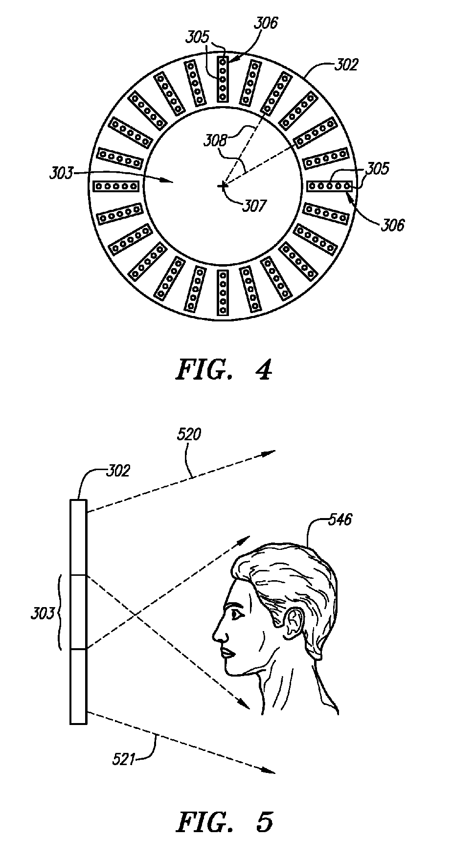
"The invention is a lighting effects system that can be used in film and photography applications. It consists of low power lights, such as LEDs or LECs, arranged on a panel or frame in a pattern to provide even, dispersive light. The panel or frame is relatively lightweight and can include circuit boards for direct mounting of the lights. The system can be controlled to adjust the intensity of each light individually or in groups, and can also be programmed to provide pre-defined patterns. Another embodiment includes a frame with a circular opening for a camera, with low power lights arranged in a pattern around the opening. The lights can be electronically controlled for differing intensity levels. Overall, the invention provides a versatile and flexible tool for creating lighting effects in film and photography."

Problems solved by technology

As one example illustrating a need for an improved lighting effects system, it can be quite challenging to provide proper illumination for the lighting of faces in television and film, especially for situations where close-ups are required.
The eyes, in particular, can provide a challenge for proper lighting.
Designing and building customized lighting systems, however, is often an expensive and time-consuming process.
However, conventional lighting systems have drawbacks or limitations which can limit their flexibility or effectiveness.
However, the mounting frames used in incandescent lighting systems are often large and ponderous, making them difficult to move around and otherwise work with.
A major drawback of incandescent lighting systems is the amount of heat generating by the incandescent bulbs.
Because of the heat intensity, subjects cannot be approached too closely without causing discomfort to the subject and possibly affecting the subject's make-up or appearance.
Also, the heat from the incandescent bulbs can heat the air in the proximity of the camera; cause a “wavering” effect to appear on the film or captured image.
Incandescent lighting may cause undesired side effects when filming, particularly where the intensity level is adjusted.
In addition to these problems or drawbacks, incandescent lighting systems typically draw quite a bit of power, especially for larger lighting systems which may be needed to provide significant wide area illumination.
Fluorescent lighting systems generate much less heat than incandescent lighting systems, but nevertheless have their own drawbacks or limitations.
For example, fluorescent lighting systems, like incandescent lighting systems, are often large and cumbersome.
Fluorescent bulbs are generally tube-shaped, which can limit the lighting configuration or mounting options.
A major drawback with fluorescent lighting systems is that the low lighting levels can be difficult or impossible to achieve due to the nature of fluorescent lights.
Consequently, fluorescent lights cannot be dimmed beyond a certain level, greatly limiting their flexibility.
In addition, fluorescent lights suffer from the same problem as incandescent lights when their intensity level is changed; that is, they tend to change in hue as the intensity changes, and film is very sensitive to alterations in lighting hue.
Because of such positioning, lighting systems may provide uneven or off-center lighting, which can be undesirable in many circumstances.
Because of their custom nature, both incandescent lighting systems and fluorescent lighting systems can be difficult to adapt to different or changing needs of a particular film project or shoot.
For example, if the director or photographer decides that a different lighting configuration should be used, or wants to experiment with different types of lighting, it can be difficult, time-consuming, and inconvenient to re-work or modify the customized lighting setups to provide the desired effects.
Furthermore, both incandescent lighting systems and fluorescent lighting systems are generally designed for placement off to the side of the camera, which can result in shadowing or uneven lighting.
A variety of lighting apparatus have been proposed for the purpose of inspecting objects in connection with various applications, but these lighting apparatus are generally not suitable for the movie, film or photographic industries.
Lighting apparatus specially adapted for illumination of objects to be inspected are generally not suitable for the special needs of the film, commercial, or photographic industries, or with live stage performances, because the lighting needs in these fields differs substantially from what is offered by object inspection lighting apparatus.
These types of apparatus are not well suited for applications requiring more precision lighting, such as film, television, and so on.
Among other things, the combination of red, green, and blue (or other) colors creates an uneven lighting effect that would generally be unsuitable for most film, television, or photographic applications.
Moreover, most of these LED-based lighting apparatus suffer from a number of other drawbacks, such as requiring expensive and / or inefficient power supplies, incompatibility with traditional AC dimmers, lack of ripple protection (when connected directly to an AC power supply), and lack of thermal dissipation.

Method used


Image

  • Versatile stand-mounted wide area lighting apparatus
  • Versatile stand-mounted wide area lighting apparatus
  • Versatile stand-mounted wide area lighting apparatus

Examples


Embodiment Construction

)

[0068]Before describing preferred embodiment(s) of the present invention, an explanation is provided of several terms used herein.

[0069]The term “lamp element” is intended to refer to any controllable luminescent device, whether it be a light-emitting diode (“LED”), light-emitting electrochemical cell (“LEC”), a fluorescent lamp, an incandescent lamp, or any other type of artificial light source. The term “semiconductor light element” or “semiconductor light emitter” refers to any lamp element that is manufactured in whole or part using semiconductor techniques, and is intended to encompass at least light-emitting diodes (LEDs) and light-emitting electrochemical cell (LECs).

[0070]The term “light-emitting diode” or “LED” refers to a particular class of semiconductor devices that emit visible light when electric current passes through them, and includes both traditional low power versions (operating in, e.g., the 20 mW range) as well as high output versions such as those operating in...


PUM


Abstract

A lighting effects system comprises an arrangement of lamp elements, such as light-emitting diodes (LEDs) or other light elements, on a panel or frame. The panel or frame may be relatively lightweight, and may include one or more circuit boards for direct mounting of the lamp elements. The panel or frame may have an opening through which a camera can view. A mounting bracket and assembly may be used for attaching the panel or frame to a camera. The lamp elements may be electronically controllable so as to provide differing intensity levels, collectively, individually, or in designated groups, and may be strobed, dimmed or otherwise controlled according to manually selected or programmable patterns. Different color lamp elements may be mounted on the same panel / frame, and, in particular, daylight and tungsten colored lamp elements may be mounted on the same panel / frame and their relative intensities selectively controlled by control circuitry.

Description

[0001]This application is a continuation of U.S. application Ser. No. 10 / 238,973 filed Sep. 9, 2002, now U.S. Pat. No. 6,948,823, which is a continuation-in-part of U.S. application Ser. No. 09 / 949,206 filed Sep. 7, 2001, now U.S. Pat. No. 6,749,310, issued Jun. 15, 2004 hereby incorporated by reference as if set forth fully herein.BACKGROUND OF THE INVENTION[0002]The field of the present invention relates to lighting apparatus and systems as may be used in film, television, photography, and other applications.[0003]Lighting systems are an integral part of the film and photography industries. Proper illumination is necessary when filming movies, television shows, or commercials, when shooting video clips, or when taking still photographs, whether such activities are carried out indoors or outdoors. A desired illumination effect may also be desired for live performances on stage or in any other type of setting.[0004]A primary purpose of a lighting system is to illuminate a subject to...

Claims


Application Information

Patent Timeline
Patent Type & Authority Patents(United States)
IPC IPC(8): G03B15/02F21S8/00F21S9/02F21V5/00F21V14/06F21V19/00F21V21/088F21V21/116G03B15/05H05B37/02H05B44/00
CPCF21K9/58G03B15/02G03B15/03G03B15/05H04N5/2256H05B33/086H05B33/0863H05B37/029F21S9/02F21V19/001F21V21/0885F21V21/116F21W2131/406F21Y2101/02F21Y2103/00G03B2215/0517G03B2215/0539G03B2215/056Y10S362/80F21V14/06F21K9/65F21Y2115/10H05B45/20H05B47/155H05B45/00H04N23/56
Inventor POHLERT, RUDYGROSSWENDT, PATFISHER, KENBAXTER, KEVIN
Owner LITEPANELS
Learn More