Electromagnetic brake

a technology of electromagnetic brake and magnet core, which is applied in the direction of spring/damper, mechanical apparatus, vibration suppression adjustment, etc., can solve the problems of reducing the braking power in this region, unable to close, and not being able to obtain braking force in this region, so as to achieve high saturation threshold of magnet core or magnet cor

Inactive Publication Date: 2008-01-22
ABB (SCHWEIZ) AG
View PDF11 Cites 1 Cited by
  • Summary
  • Abstract
  • Description
  • Claims
  • Application Information

AI Technical Summary

Benefits of technology

[0013]The device according to the invention shall be designed in such a way that the saturation threshold of the magnet core or the magnet cores is high, that is that a relatively powerful magnetic field can be formed without saturation of the magnetic core or cores.

Problems solved by technology

In that way, a magnetic field that covers generally the whole width of the melt can be obtained, However, the induced current in a region adjacent to the short sides will not be able to become closed, but will depart from the molten metal through the shorts side.
This, in its turn, results in the braking force f not being obtained in this region.
A drawback of the disclosed arrangement, in particular when combined with conventional brake devices located along the broad sides, is that the magnetic field thereby created has such a direction that at least a substantial part of the current induced in the region close to the short sides still has a tendency not to get closed, resulting in a reduced braking power f in this region.

Method used


Image

  • Electromagnetic brake
  • Electromagnetic brake
  • Electromagnetic brake

Examples


Embodiment Construction

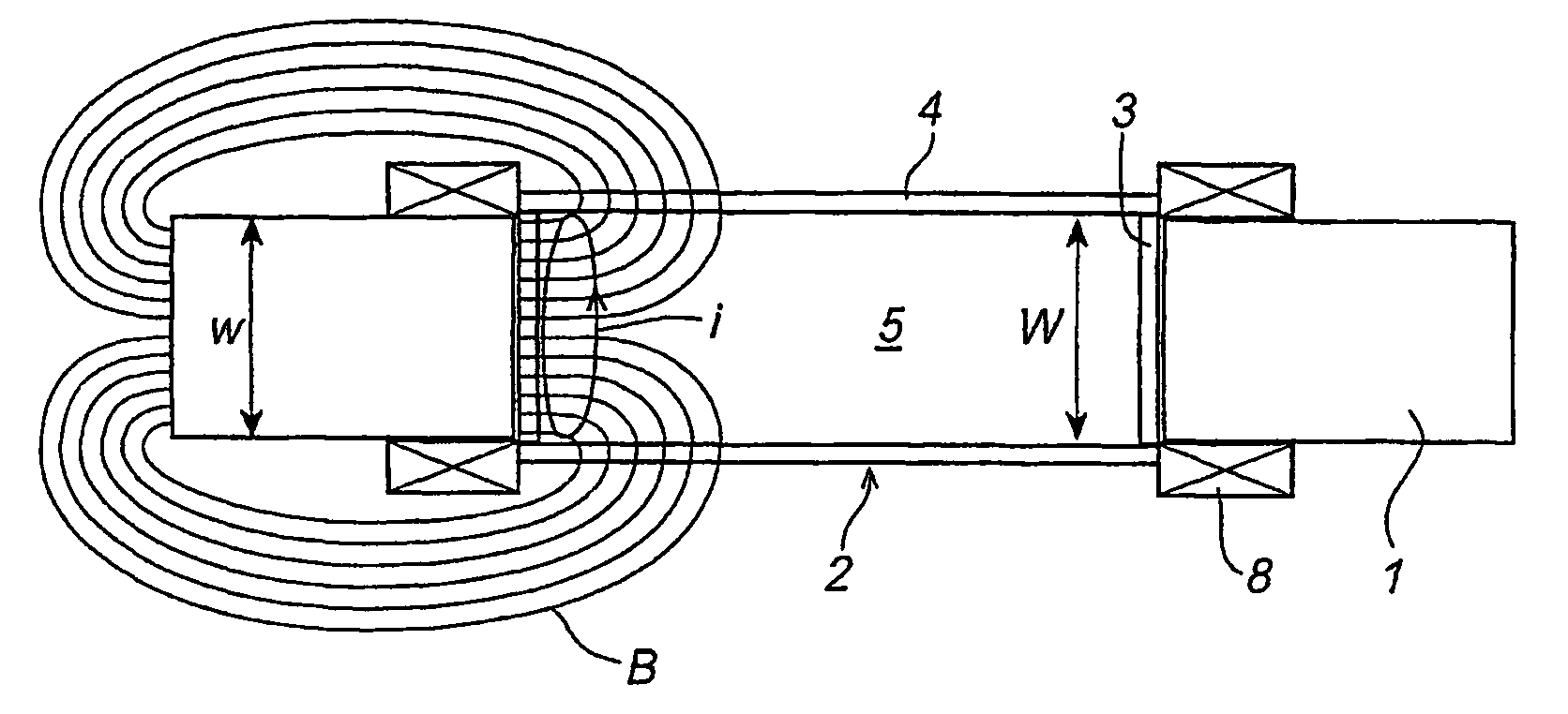
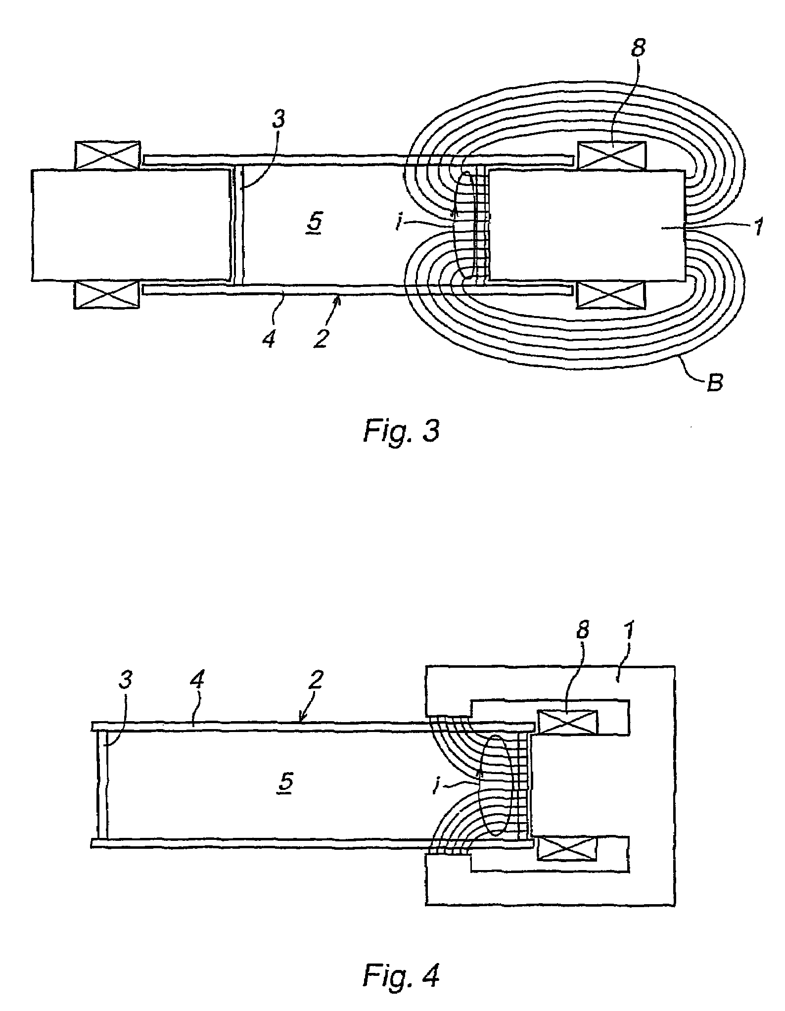
[0029]FIGS. 1-3 show a first embodiment of the device according to the invention. The device comprises two magnetic cores 1, for example iron cores, that are arranged at a mould, a copper mould 2.

[0030]The mould 2 has opposite short sides 3 and broad sides 4. Preferably, it is made of a copper alloy with a very high percentage of copper. The mould 2 is arranged vertically and open in the top and in the bottom for the purpose of permitting a continuous or semi-continuous casting of metal, for example steel, therein.

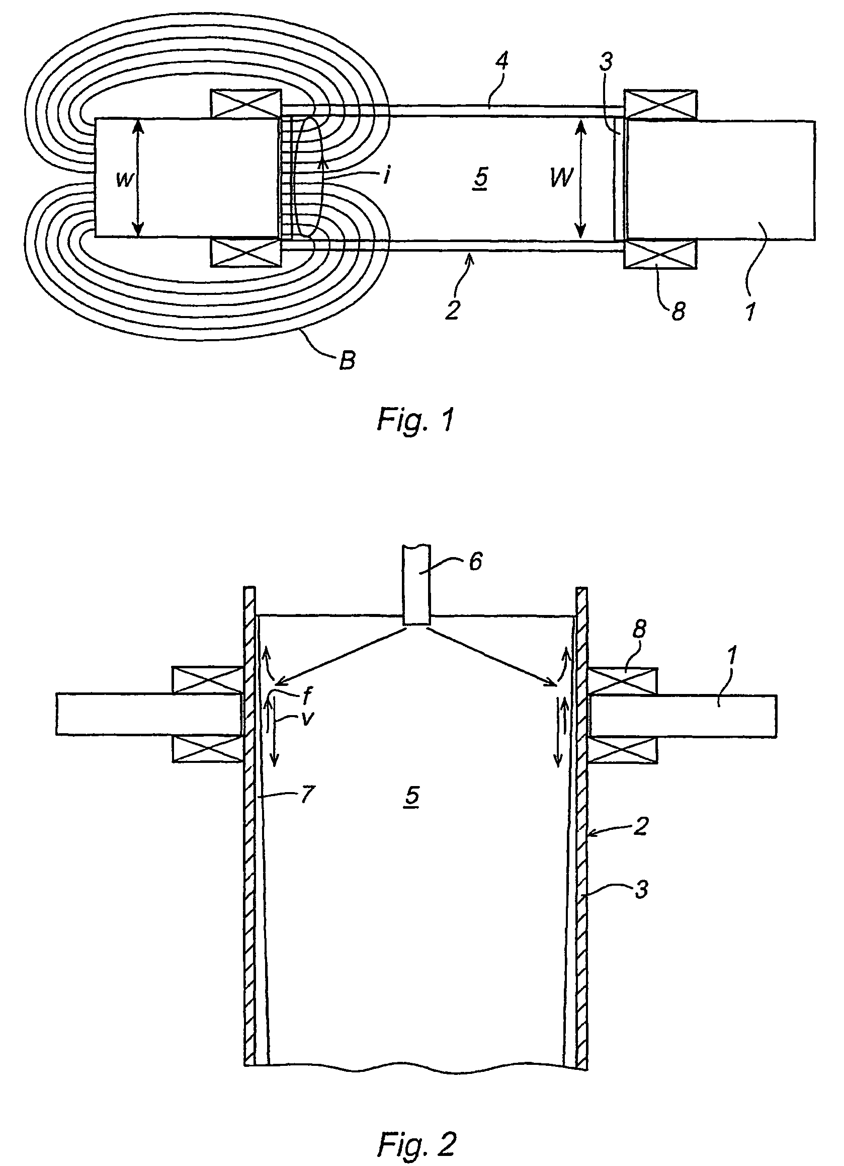
[0031]A melt 5 of metal is delivered to the mould through a tube 6 that extends down into the mould from above. The molten metal 5 is permitted to move downwards through the mould 2, while it solidifies and forms a skin 7 at its periphery. In a region (impinging point) below the end of the casting tube 6, the down-flowing molten metal 5 impinges the inner walls of the short sides 3 with an oblique angle and with a raised velocity. Thereby, a part of the molten metal 5 is g...


PUM

PropertyMeasurementUnit
magnetic fieldaaaaaaaaaa
widthaaaaaaaaaa
magnetic fieldsaaaaaaaaaa

Abstract

A device for braking a flow of molten metal (5) in a device for continuous or semi-continuous casting of metals in a mould (2) which is provided with opposite broad sides (4) and opposite short sides (3), said device comprising at least one magnet core (1), said at least one core facing one of the short sides (3) of the mould (2) for the purpose of generating a magnetic field (B) and an induced current (i) in a region of the molten metal (5) adjacent the short side (3). The core (1) is arranged in such a way that the magnet field (B) which is generated in said region generally has a direction perpendicular from the short side (3) of the mould (2) towards the centre of the latter.

Description

TECHNICAL FIELD[0001]The present invention relates to a device for breaking a flow of molten metal in a device for continuous or semi-continuous casting of metals in a mould which is provided with opposite broad sides and opposite short sides, said device comprising[0002]at least one magnet core,[0003]said at least one core facing one of the short sides (3) of the mould for the purpose of generating a magnetic field and an induced current in a region of the molten metal adjacent to the short side.[0004]The invention also relates to a method for braking a flow of molten metal in a device for continuous or semi-continuous casting of metals in a mould which is provided with opposite broad sides and opposite short sides.BACKGROUND OF THE INVENTION[0005]In devices for continuous or semi-continuous casting, it is a well-known fact to brake the flow of metal in a mould by applying one or more magnetic fields to the molten metal. A plurality of different brake configurations have been propo...

Claims


Application Information

Patent Timeline
Patent Type & Authority Patents(United States)
IPC IPC(8): B22D27/02B22D11/00B22D11/04B22D11/11B22D11/115
CPCB22D11/115
Inventor LEHMAN, ANDERS
Owner ABB (SCHWEIZ) AG
Why Eureka
Try Eureka