Method of controlling a brushless permanent-magnet motor

a permanent magnet, brushless technology, applied in the direction of electric motor control, electric motor control, control system, etc., can solve the problem of missing the aligned position altogether, and achieve the effect of increasing the saturation threshold

Active Publication Date: 2017-10-26
DYSON TECH LTD
View PDF4 Cites 5 Cited by
  • Summary
  • Abstract
  • Description
  • Claims
  • Application Information

AI Technical Summary

Benefits of technology

[0007]The saturation threshold could conceivably be set such that the measured parameter is less that the saturation threshold only when the rotor is at or very near the aligned position. The controller would then immediately commutate the phase winding when the measured parameter is less than the saturation threshold. However, a difficulty with this approach is that, if the saturation threshold is set too low, the controller may fail to detect that the measured parameter is less than the saturation threshold and thus miss the aligned position altogether. The saturation threshold is therefore set to a higher value such that the measured parameter is less than the saturation threshold after the rotor rotates through a smaller angle. For example, the saturation threshold may be set such that the measured parameter is less than the saturation threshold after the rotor rotates through 160 electrical degrees rather than 180 electrical degrees. The commutation period is then set such that the rotor rotates through the remaining angle, e.g. 20 electrical degrees. As a result, the phase winding is commutated at the aligned position. By employing a higher saturation threshold (i.e. one that corresponds to, say, 160 electrical degrees rather than 180 electrical degrees), the method is less likely to miss a saturation event (i.e. the point at which the measured parameter is less than the saturation threshold). As a result, the phase winding is commutated more reliably at the aligned position.

Problems solved by technology

However, a difficulty with this approach is that, if the saturation threshold is set too low, the controller may fail to detect that the measured parameter is less than the saturation threshold and thus miss the aligned position altogether.

Method used


Image

  • Method of controlling a brushless permanent-magnet motor
  • Method of controlling a brushless permanent-magnet motor
  • Method of controlling a brushless permanent-magnet motor

Examples


Embodiment Construction

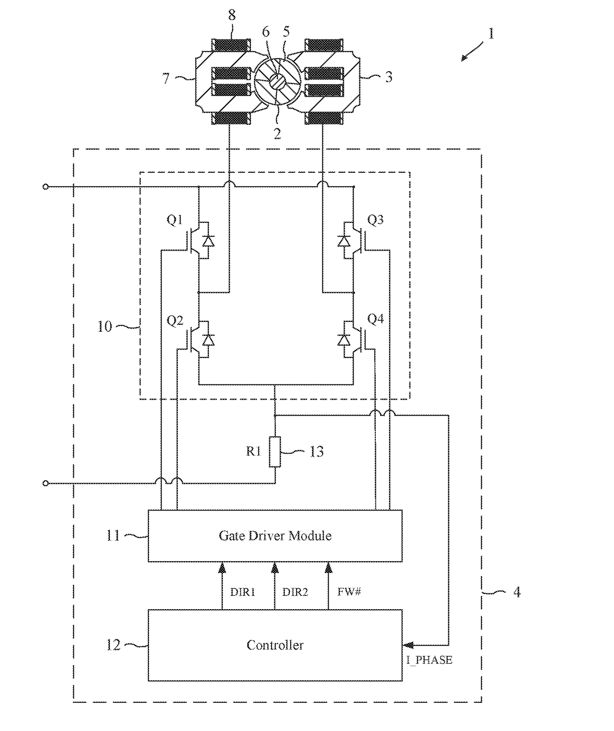
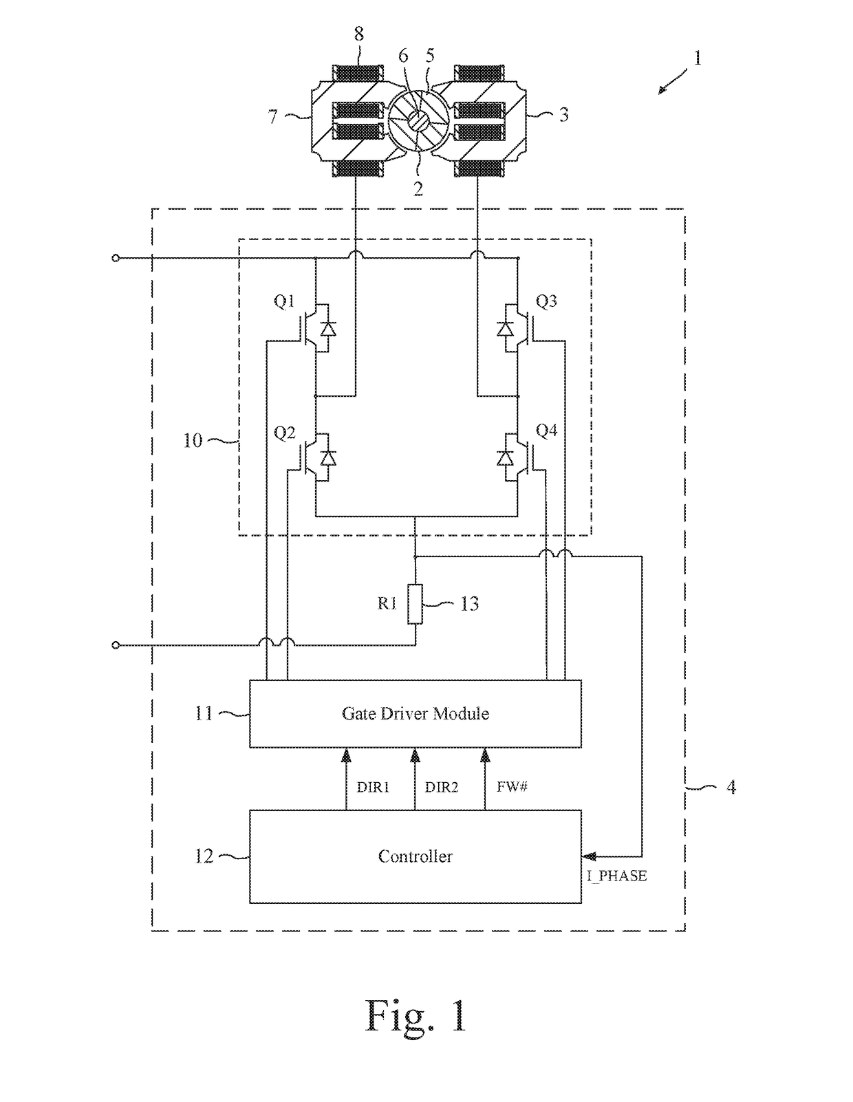
[0013]The permanent-magnet motor 1 of FIG. 1 comprises a rotor 2, a stator 3, and a control system 4.

[0014]The rotor 2 comprises a four-pole permanent magnet 5 secured to a shaft 6. The stator 3 comprises a pair of cores 7 having four salient poles, and a phase winding 8 wound about the cores 7.

[0015]The control system 4 comprises an inverter 10, a gate driver module 11, a controller 12, and a current sensor 13.

[0016]The inverter 10 comprises a full bridge of four power switches Q1-Q4 that couple the phase winding 8 to the voltage rails of a power supply (not shown).

[0017]The gate driver module 11 drives the opening and closing of the switches Q1-Q4 in response to control signals output by the controller 12.

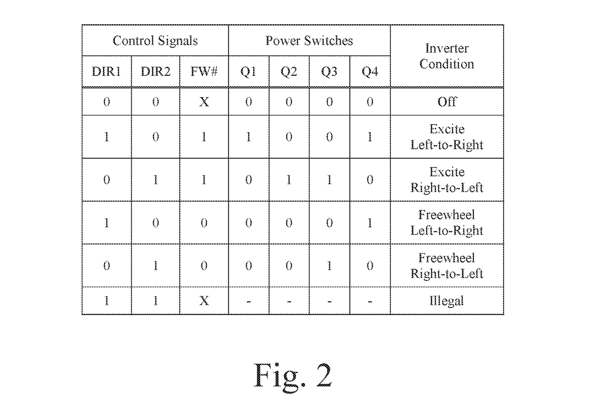
[0018]The controller 12 is responsible for controlling the operation of the motor 1 and generates three control signals: DIR1, DIR2, and FW#. The control signals are output to the gate driver module 11, which in response drives the opening and closing of the switches Q1-Q4.

[0019]...


PUM


Abstract

A method of controlling a brushless permanent-magnet motor that includes sequentially exciting and freewheeling a phase winding of the motor is provided. The phase winding is freewheeled when the phase current exceeds an upper threshold. The method further includes measuring a parameter that corresponds to either: (i) the magnitude of the phase current during or at the end of freewheeling when the phase winding is freewheeled for the fixed period of time, or (ii) the time interval during freewheeling or during excitation when the phase winding is freewheeled until the phase current falls below the lower threshold. The measured parameter is then compared against a saturation threshold, and the rotor is determined to be at a predetermined position. In response to determining that the rotor is at the predetermined position, the phase winding is commutated after a commutation period has elapsed.

Description

REFERENCE TO RELATED APPLICATION[0001]This application claims the priority of United Kingdom Application No. 1607288.6, filed Apr. 26, 2016, the entire contents of which are incorporated herein by reference.FIELD OF THE INVENTION[0002]The present invention relates to a method of controlling a brushless permanent-magnet motor.BACKGROUND OF THE INVENTION[0003]Knowledge of the rotor position is essential in order to commutate the phase windings of a brushless motor at the correct times. A permanent-magnet motor will often include a Hall-effect sensor, which outputs a signal indicative of the rotor position. Although the component cost of the sensor is relatively cheap, integrating the sensor within the motor often complicates the design and manufacture of the motor. Additionally, the signal output by the sensor is often susceptible to electromagnetic noise generated within the motor.[0004]Sensorless schemes for determining indirectly the position of a rotor are known. For a permanent-m...

Claims


Application Information

Patent Timeline
Patent Type & Authority Applications(United States)
IPC IPC(8): H02P6/28
CPCH02P2205/01H02P6/28H02P6/18H02P6/185H02P6/26
Inventor ZHENG, LIBO
Owner DYSON TECH LTD
Why Eureka
Try Eureka