Ball chain

a ball chain and chain technology, applied in the field of ball chains, can solve the problems of affecting the wall of the return path of the spacer at both ends of the chain, the inconvenient process, and the difficulty of making a seamless circular chain, so as to improve the operating smoothness of the chain and suppress the axial distortion of the chain

Active Publication Date: 2008-01-22
HIWIN TECH
View PDF7 Cites 12 Cited by
  • Summary
  • Abstract
  • Description
  • Claims
  • Application Information

AI Technical Summary

Benefits of technology

[0017]The primary objective of the present invention is to solve the aforesaid problems by providing a ball chain, wherein both ends of the ball chain are connected by connecting blocks that are parallel to the center of the radius of curvature of return paths, so as to suppress the axial distortion of the chain, and to improve the operating smoothness of the chain.
[0019]The third objective of the present invention it to provide a ball chain, wherein each of the spacers is a flat and circular structure, so as to reduce the contact surface between the spacers and the balls, thus reducing momentum waste.
[0020]To obtain the abovementioned objective, the present invention provides a ball chain, at either end of the chain is formed a protruded connecting block, the connecting blocks each has an abutting surface, and the abutting surfaces are parallel to a radial direction of a center of the radius of curvature of the ball chain (namely the center of the radius of curvature of the return path), the abutting surfaces of the connecting blocks of the spacers at both ends of the chain are mated with each other, thus limiting axial rotation of the ball chain, so that when the ball chain moves in the return path, the abutting surfaces of the two connecting blocks will keep contacting each other. Due to the two connecting blocks at the end of the ball chain that has entered the return path are protrusive and are engaged in the groove, the end of the chain within the return path will use the abutting surface to limit the end of the chain that has not entered the return path and to guide the end of the chain, which has not entered the return path, into the return path smoothly, thus improving the operating smoothness of the chain.
[0024]In addition, the spacers of the present invention are flat structure, so that the balls are in a line contact relation to the spacers, by such arrangement, the contacting surface between the balls and the spacers can be reduced to the least, thus preventing an increase in the waste of momentum.

Problems solved by technology

However, in real application, it is difficult to make a seamless circular chain, therefore, the chain is usually made in the form a long and narrow chain, and then both ends of the chain are connected together, forming a circle.
Such process is very inconvenient.
However, the chain with an interval left between both ends thereof will form a free end at the both ends, it will cause a problem that the protruding spacers at both ends of the chain will impact the wall of the return path.
And the chain will be pushed, pulled and distorted constantly when it drives the balls to move, therefore, it will have a problem of axial distortion of the chain.
Both ends of the aforementioned various chain structures are axially connected, and the problem of radial distortion cannot be solved.
As a result, the chain and the balls cannot move smoothly.

Method used


Image

  • Ball chain
  • Ball chain
  • Ball chain

Examples


Embodiment Construction

[0046]The foregoing, and additional objects, features and advantages of the present invention will become apparent from the following detailed description of preferred embodiments thereof, taken in conjunction with the accompanying drawings.

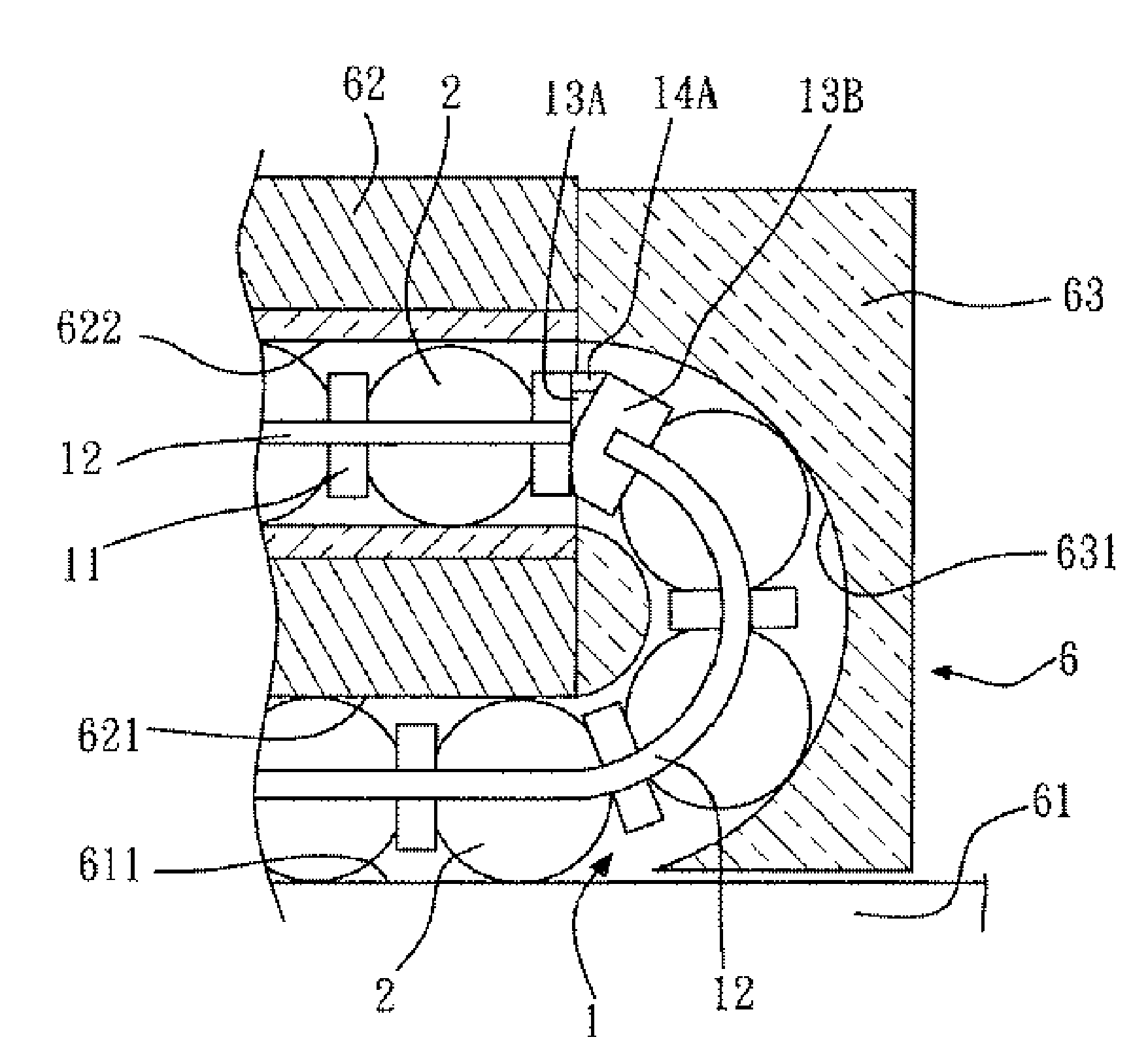
[0047]Referring firstly to FIGS. 5 and 6, a ball chain 1 in accordance with the present invention is used in a linear guideway 6. The linear guideway 6 comprises a rail 61, a sliding block 62 and two caps 63 at both ends of the sliding block 62. In the rail 61 is formed a plurality of rolling tracks 611 for the balls 2. The sliding block 62 is formed with a plurality of ball grooves 621 for cooperating with the rolling tracks 611, and a plurality of circulation passages 622 for the balls 2. In each of he caps 63 is formed a return path 631 for jointing the circulation passages 622 to the ball grooves 621.

[0048]The ball chain in accordance with the present invention comprises a plurality of spacers 11 each of which is a hollow ring-shaped structur...


PUM


Abstract

A ball chain used in a linear guideway, at either end of the chain is formed a protruded connecting block, the connecting blocks each has an abutting surface that is parallel to a radial direction of a center of the radius of curvature of the ball chain, the abutting surfaces of the connecting blocks of the spacers at both ends of the chain are mated with each other for limiting axial rotation of the ball chain. Due to the two connecting blocks at the end of the ball chain that has entered the return path protrude out of the groove, the end of the chain within the return path will use the abutting surface to limit the end of the chain that has not entered the return path and to guide the end of the chain, which has not entered the return path, into the return path smoothly, thus improving the operating smoothness of the chain.

Description

BACKGROUND OF THE INVENTION[0001]1. Field of the Invention[0002]The present invention relates to a ball chain, and more particularly to a ball chain that is used in a linear guideway, and both ends of the chain are radially mated each other, such arrangement can suppress axial rotation of the ball chain and can improve the operating smoothness of the ball chain.[0003]2. Description of the Prior Art[0004]Referring to FIG. 1, which shows a chain structure 8 that is used in linear guideway to connect a plurality of balls in series. The chain structure 8 includes a plurality of spacers 81 used to separate two neighboring balls 7, and two connecting members 82 are arranged in the axial direction of the chain structure for connecting the plurality of spacers 81 together in series. Each of the spacers 81 is defined with a spherical concave 811 for mating with the balls 7, so that the balls 7 can be retained between two spacers 81.[0005]Referring to FIGS. 2 and 3, a linear guideway 9 compri...

Claims


Application Information

Patent Timeline
Patent Type & Authority Patents(United States)
IPC IPC(8): F16C29/06
CPCF16C29/0638F16C33/3825
Inventor KUO, CHANG-HSINLAI, CHIEN-KUEN
Owner HIWIN TECH
Why Eureka
Try Eureka