Ball screw

Active Publication Date: 2019-07-11
HIWIN TECH
View PDF12 Cites 2 Cited by
  • Summary
  • Abstract
  • Description
  • Claims
  • Application Information

AI Technical Summary

Benefits of technology

[0004]The present invention has been accomplished under the circumstances in view. It is the main object of th

Problems solved by technology

However, during the return of the balls, the impact force on the return tube has a great concern with the angle of the balls off the load path.
If the impact force is too large, it will inevitably affect

Method used


Image

  • Ball screw
  • Ball screw
  • Ball screw

Examples


Embodiment Construction

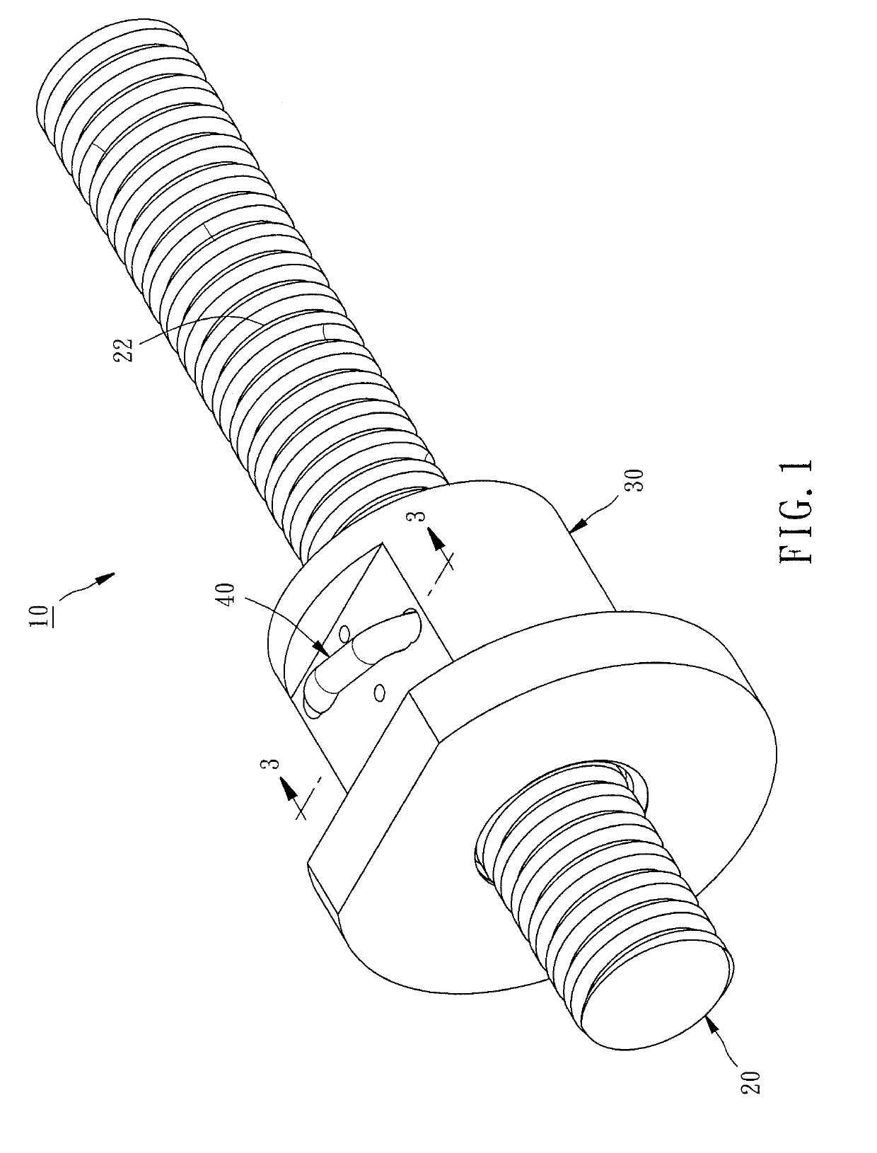
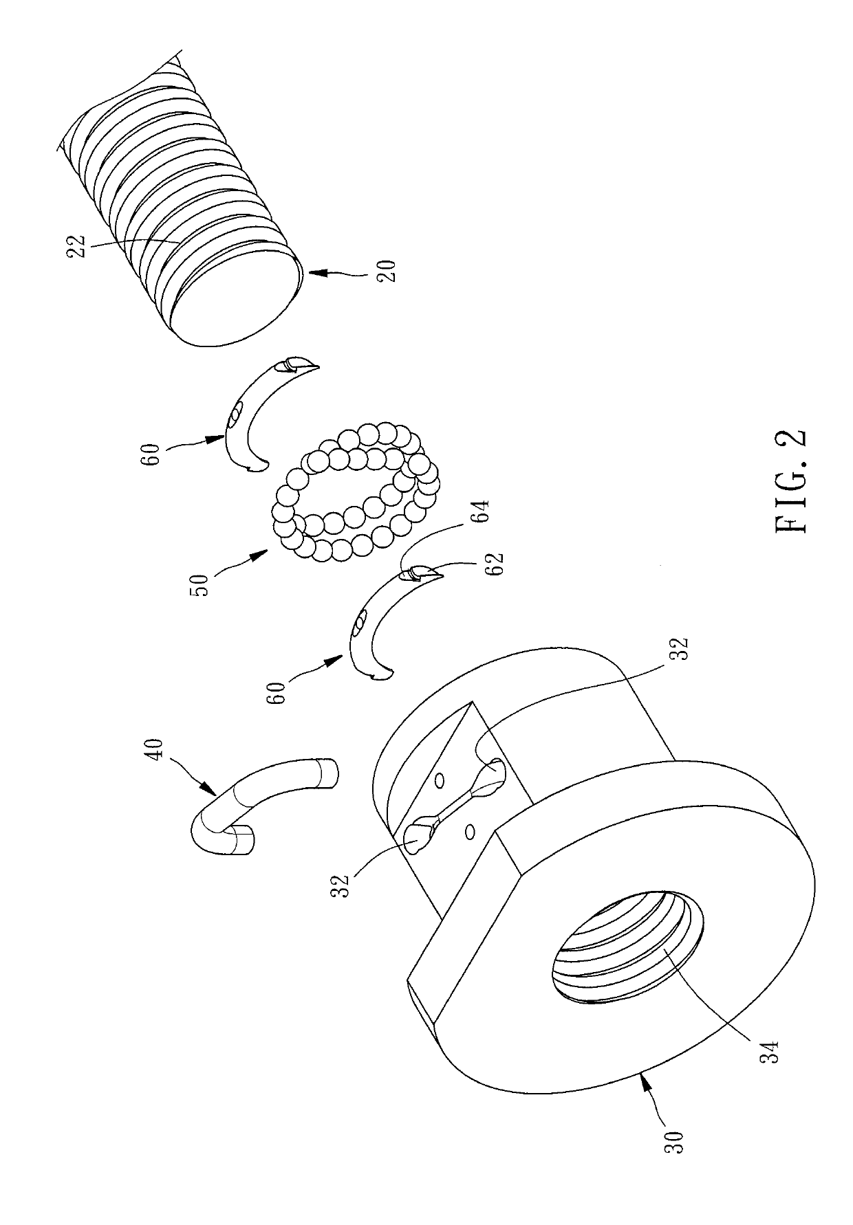
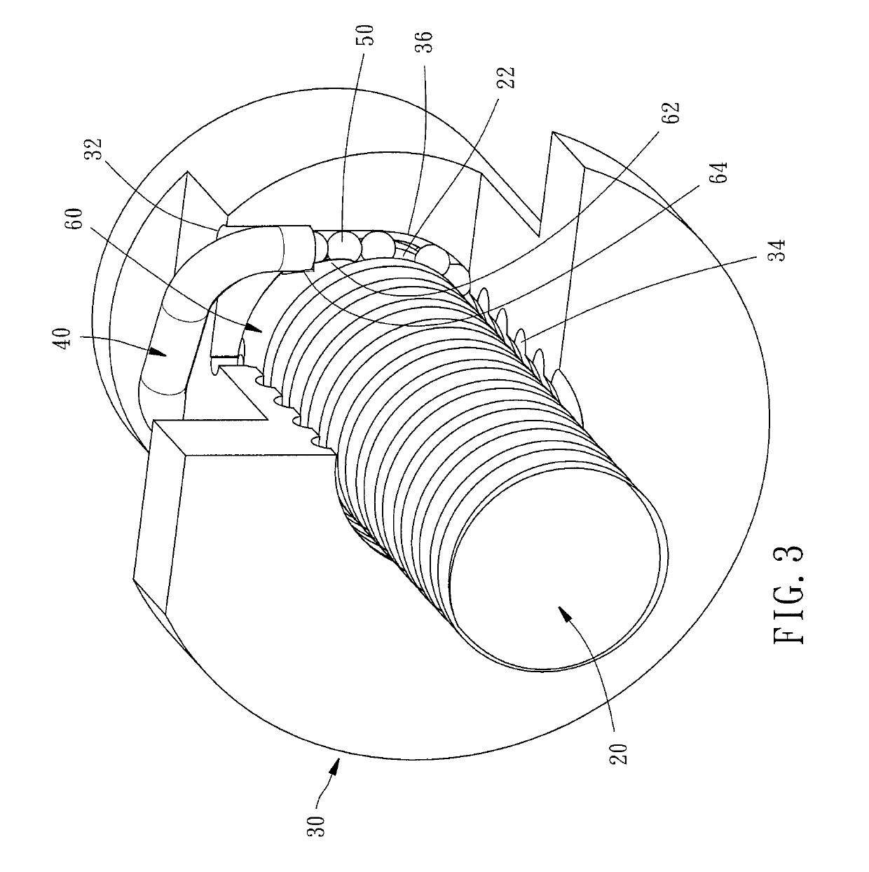
[0019]Referring to FIGS. 1-3, a ball screw 10 in accordance with a first embodiment of the present invention is shown. As illustrated, the ball screw 10 comprises a screw shaft 20, a screw nut 30, a return tube 40, a plurality of rolling members 50 and two deflectors 60.

[0020]The screw shaft 20 comprises an external thread groove 22 around the periphery thereof.

[0021]The screw nut 30 is threaded onto the screw shaft 20 for axial movement along the screw shaft 20. The screw nut 30 comprises two mounting holes 32 located on an outer peripheral surface thereof, an internal thread groove 34 spirally extended around an opposing inner peripheral surface thereof and defining with the external thread groove 22 of the screw shaft 20 a load path 52 (see FIG. 4), a guide groove 36 located on the inner peripheral surface corresponding to one respective mounting hole 32 and defining with a respective part of the external thread groove 22 of the screw shaft 20 a respective non-load path 54 (see F...


PUM


Abstract

A ball screw includes a load path and a non-load path defined between the screw shaft and the screw nut with the two ends of the non-load path respectively connected to the load path and a reflow channel of the return tube. The ball screw defines an imaginary horizontal plane and an imaginary sloping surface that are intersected with each other at the center axis of the screw shaft. The imaginary horizontal plane passes through the non-load path. The imaginary sloping surface passes through the junction between the non-load path and the load path. The imaginary sloping surface defines a negative included angle within 1˜3 degrees with respect to the imaginary horizontal plane to reduce the impact force rendered by each rolling member to the return tube, enhancing operational smoothness and reducing operational noise.

Description

BACKGROUND OF THE INVENTION1. Field of the Invention[0001]The present invention relates to ball screw technology and more particularly, to a ball screw that effectively improves operational smoothness and reduces operation noise.2. Description of the Related Art[0002]Ball screw achieves high-precision transmission by means of rolling movement of balls in between a screw shaft and a screw nut. In order to cooperate with the rolling path of the ball, the ball screw is provided with a return tube in the screw nut so that the balls can pass through the reflow channel of the return tube to achieve the reflow effect after getting off the load path between the screw shaft and the screw nut.[0003]However, during the return of the balls, the impact force on the return tube has a great concern with the angle of the balls off the load path. If the impact force is too large, it will inevitably affect operational smoothness and production of noises. Therefore, how to change the ball off-angle to...

Claims


Application Information

Patent Timeline
IPC IPC(8): F16H25/22
CPCF16H25/2219F16H25/22F16H25/24F16H25/2214
Inventor YANG, CHIA-MINGLIN, YEN-WEI
Owner HIWIN TECH
Why Eureka
Try Eureka