V-belt system

A technology of toothed pulleys and pulleys, applied in the directions of V-belts, transmission belts, belts/chains/gears, etc., can solve the problem of not specifying the shape of the synchronous belt

Inactive Publication Date: 2005-01-05
THE GATES CORP
View PDF1 Cites 2 Cited by
  • Summary
  • Abstract
  • Description
  • Claims
  • Application Information

AI Technical Summary

Problems solved by technology

The prior art does not describe a timing belt-shaped belt with a V-belt section for power transmission.

Method used


Image

  • V-belt system
  • V-belt system

Examples


Embodiment Construction

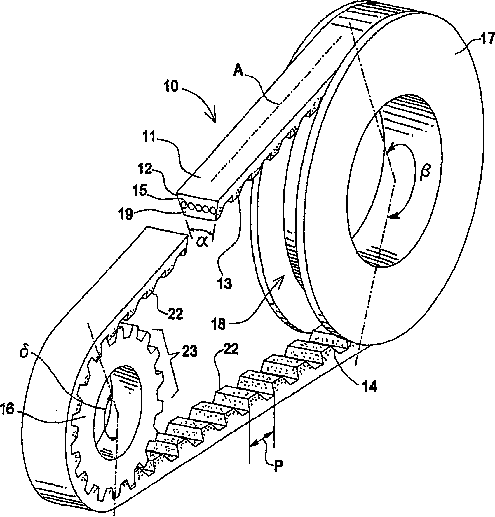
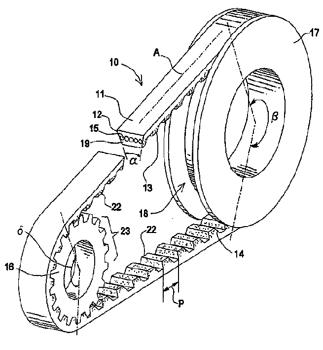
[0020] Referring to the drawings, an endless member or belt 10 is shown connected in series between a timing toothed pulley 16 and a V-belt pulley 17 . The synchronous toothed pulley 16 and the V-belt pulley 17 are connected on the rotating shaft (not shown) as required by the user. Belt 10 includes an upper belt layer 11 and a lower belt layer 19 . Each upper belt layer 11 and lower belt layer 19 comprises any material known in the timing or V-belt art, including but not limited to elastomeric or urethane materials. Belt 10 also includes a stretch belt layer 15 . The tensile tape layer 15 is arranged parallel to the main axis A of the tape. The tensile belt layer comprises any material known in the timing or V-belt art, including but not limited to fiberglass, aramid, nylon, polyester or PBO. The stretch tape layers may be twisted or braided.

[0021] The elastomeric material also incorporates short fibers (not shown) extending from the sides 12 , 13 . The short fibers r...


PUM

PropertyMeasurementUnit
lengthaaaaaaaaaa
diameteraaaaaaaaaa

Abstract

The invention comprises a synchronous v-belt. The belt (10) has a pulley engaging surface (13) having a toothed or cogged profile for engaging a synchronous pulley (16). The pulley engaging surface (13) further comprises a cover layer to increase belt life and reduce noise. The belt (10) also has opposing sides cut, ground or molded to describe an included angle (a) for engaging a v-belt or single groove pulley (17). The belt (10) is preferably used in conjunction with one synchronous pulley (16) and one v-belt pulley (17). The belt meshes with the teeth (23) of the synchronous pulley (16) and simultaneously runs in the groove (18) of the v-belt pulley (17). On start up, the v-belt (10) may slip slightly in the v-grouve pulley (17), thereby reducing the initial start up shock to the system. Therefore, the limit for power transmission in now the size and angle ( beta ) of wrap of the larger v-belt pulley (17). In addition, the synchronous drive pulley (16) provides a positive mechanical belt drive interface which, in conjunction with the larger v-blet pulley (17), allows up to 30% more torque to be transmitted by the inventive belt while reducing operating noise, depending upon the system design parameters.

Description

technical field [0001] The present invention relates to a synchronous V-belt system. Background technique [0002] Belt driven power transmission mechanisms are typically implemented using one of two types of belts. They are usually timing belts or V-belts. Timing belts include belts with a plurality of teeth or teeth on the pulley engaging surfaces. The teeth or teeth engage the toothed pulley. The timing belt actually engages the pulley in which it is cascaded, thus enabling high torque transmission. [0003] The V-belt comprises a belt having sides cut at a predetermined angle. The sides of the belt are tandem in a single groove of a V-groove pulley. They operate at low torque but are able to operate more quietly than the timing belt. Also under load the V-belt will slip when the applied load exceeds the power transmission capability of the pulley with the smallest diameter or surrounding circumference. Therefore, the transmitted horsepower or maximum torque is det...

Claims


Application Information

Patent Timeline
Patent Type & Authority Patents(China)
IPC IPC(8): F16G1/28F16G5/06F16G5/20F16H7/02
CPCF16G1/28F16G5/20F16H7/023
Inventor A·克拉克
Owner THE GATES CORP
Why Eureka
Try Eureka