
Cardan shaft structure with tightness adjustable functions

a cardan shaft and adjustable function technology, applied in the field of universal joint technology, can solve the problem of limit the action force generated by the spring, and achieve the effect of reducing maintenance costs and increasing convenien

Inactive Publication Date: 2008-01-22
SERCOMM
View PDF25 Cites 43 Cited by
  • Summary
  • Abstract
  • Description
  • Claims
  • Application Information

AI Technical Summary

Benefits of technology

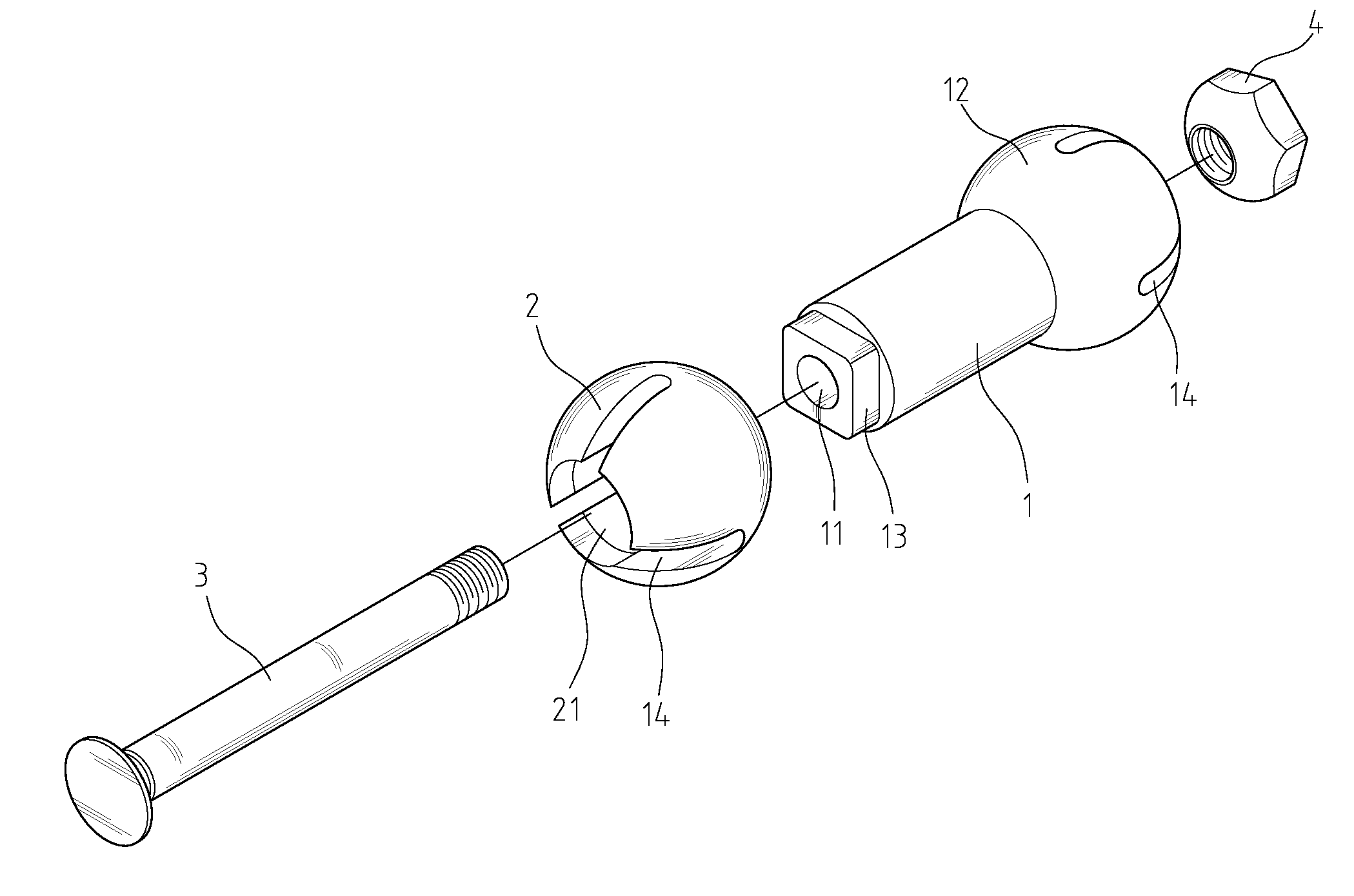
The present invention solves the problem of limited adjustable range and imperfect fixed force after adjustment in traditional cardan shaft structures. It achieves this by using a cardan shaft structure with tightness adjustable functions. The structure includes a body, two spheres, a bolt, and a nut. The spheres are coupled with both ends of the body, and the body has a through-hole penetrating through both spheres at its both ends, with grooves equipped into the side walls of the spheres. The grooves separate each sphere into several portions equally. The inner wall of the clamping plate is pushed against while the sphere is being expanded. The angle degree of the cardan shaft is adjustable by turning the clamping component while the inner wall of the clamping plate is being loosened. This structure is simpler and more convenient than traditional universal joint devices and reduces maintenance cost.

Problems solved by technology

In addition, there are bearing plate C and spring D installed for connecting inner area in-between the sphere head A and the body, and hence frictional action force will be generated further in-between bearing plate C and sphere head A by the time the spring D is pushing against bearing plate C. Therefore, when it is combined with adjusting the angle for ferrule A2 of the sphere head, the ferrule A2 will be fixed and locked automatically if the bearing plate C is pushing against the sphere head A. However, there is a limitation on action force generated by the spring.

Method used


Image

  • Cardan shaft structure with tightness adjustable functions
  • Cardan shaft structure with tightness adjustable functions
  • Cardan shaft structure with tightness adjustable functions

Examples


Embodiment Construction

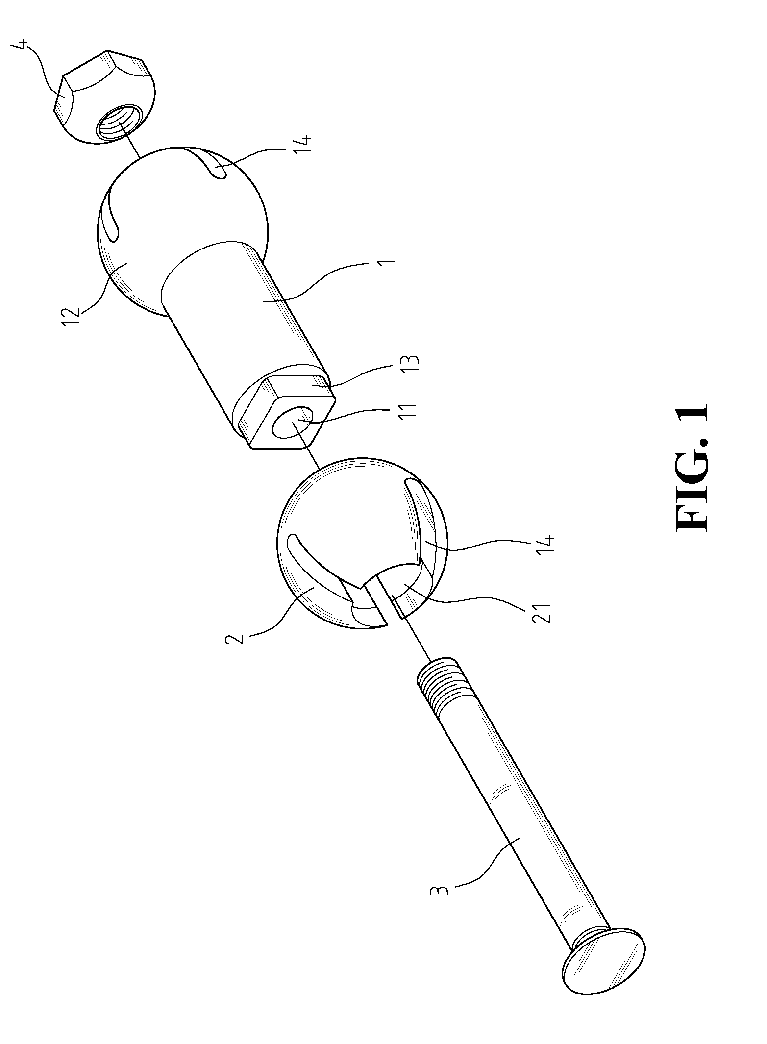
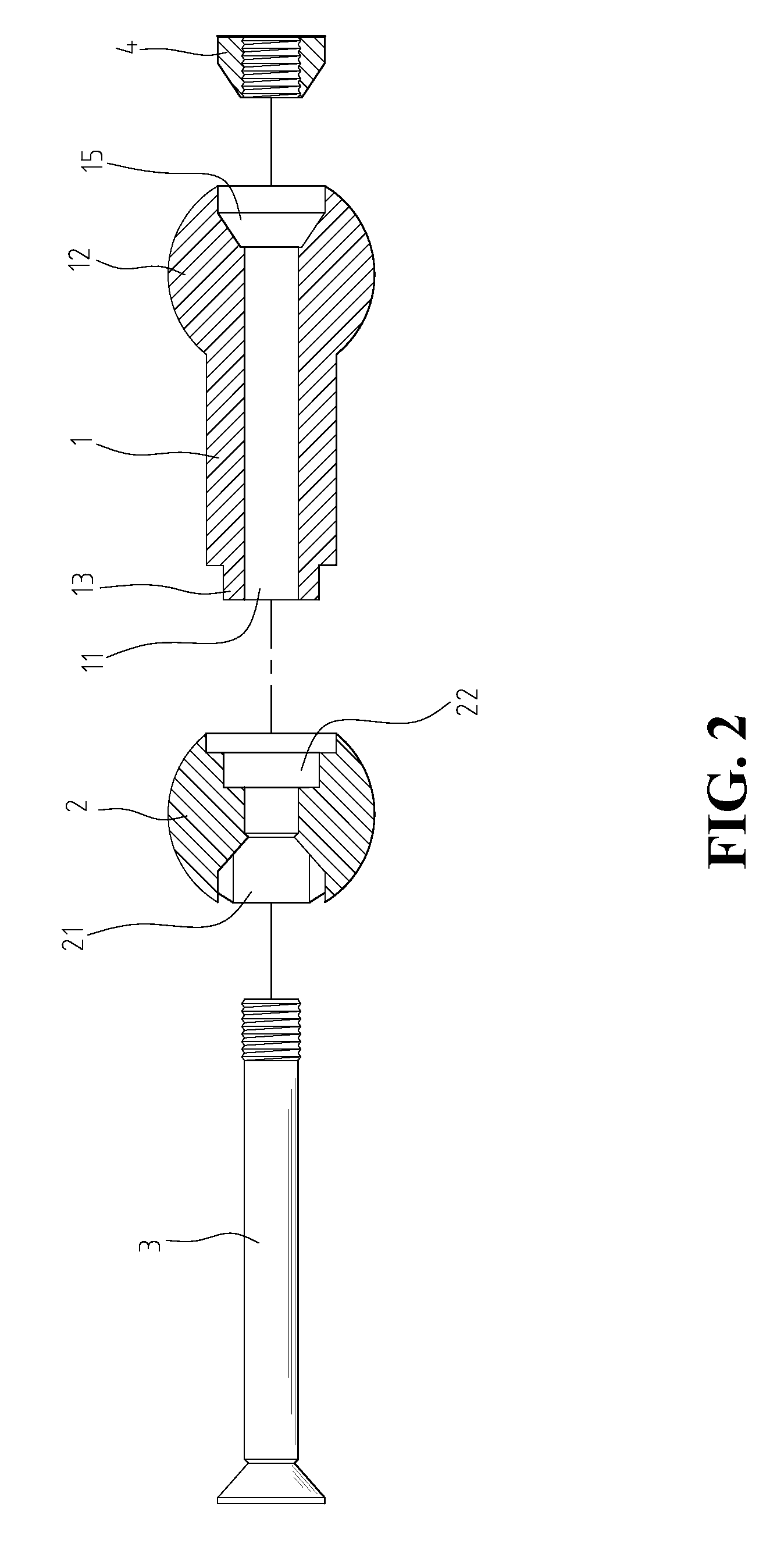
[0016]With reference to both FIG. 1 and FIG. 2, it is an exploded view of the preferred embodiment of the present invention, wherein the present invention comprises a body 1 having two spheres 2, 12 located at its two ends respectfully. One of the spheres is being fixed at one end of the body 1, and the other sphere 2 is separated from the body. The body 1 has a through-hole 11 located at its center portion, and penetrating through its two ends and the two spheres. There are a plurality of grooves 14 equipped at the side wall of fin sphere 12. In addition, there is a socket portion 15 equipped at the central hole at the end of the sphere 12 (as shown on FIG. 2). At another end of body 1, there is an extended portion 13, where the extended portion 13 can be either a square shape or multilateral shape. There is a recess portion 22, complementary to the extended portion 13, located at one end of the separated sphere 2, in such a way that the extended portion 13 and the recess portion 2...


PUM


Abstract

A cardan shaft structure with tightness adjustable functions has a through-hole passing through spheres located at both ends of the cardan shaft body, and a taper socket respectively installed into the opening end of each sphere. A bolt is inserted into both spheres and the body, fixed and locked together in conjunction with a nut. The cardan shaft structure works together with two clamping components wrapping around the spheres. When the sphere is being pushed against (or freed from) the inner wall of the clamping component by tightening (or loosing) the bolt so as to make the sphere either expand (or recover), the angle displacement of the clamping component becomes adjustable accordingly.

Description

BACKGROUND OF THE INVENTION[0001]1. Field of the Invention[0002]The present invention relates generally to the field of a universal joint technology, which is used for the purpose of angle adjustment.[0003]2. The Prior Arts[0004]In light of many different situations, it usually needs a universal joint device to solve the problem of dead angles on some actions.[0005]According to FIG. 5, it shows a known universal joint structure, which has a sphere head A located internally in a body, where the sphere head A has a quadrant orifice A1 penetrating through both ends, and the sphere head A is being linked to the body by a spline shaft B which is penetrating through the quadrant orifice A1. In addition, there are bearing plate C and spring D installed for connecting inner area in-between the sphere head A and the body, and hence frictional action force will be generated further in-between bearing plate C and sphere head A by the time the spring D is pushing against bearing plate C. Theref...

Claims


Application Information

Patent Timeline
Patent Type & Authority Patents(United States)
IPC IPC(8): A61B17/56F16C11/06
CPCF16C11/106F16M11/14F16M11/2078F16C11/0609Y10T403/32204Y10T403/5793Y10T403/32196Y10T403/32631Y10T403/557Y10T403/32565
Inventor CHANGYU, YI-FEI
Owner SERCOMM
Learn More