Gripping devices

Inactive Publication Date: 2008-01-22
VAGN ERIK DALL
View PDF13 Cites 66 Cited by
  • Summary
  • Abstract
  • Description
  • Claims
  • Application Information

AI Technical Summary

Benefits of technology

[0010]Roughened surfaces are referred to above for enhancing the locking engagement to hold the body axially in the sleeve. Such surfaces can also be used when a liner is included. Flexible peripheral teeth can be employed, but it is preferred to form the relevant surfaces with complementary annular grooves. The grooved sur

Problems solved by technology

However, as such rotational movement can be rather cumbersome in the circumstances of a surgical o

Method used


Image

  • Gripping devices
  • Gripping devices
  • Gripping devices

Examples


Embodiment Construction

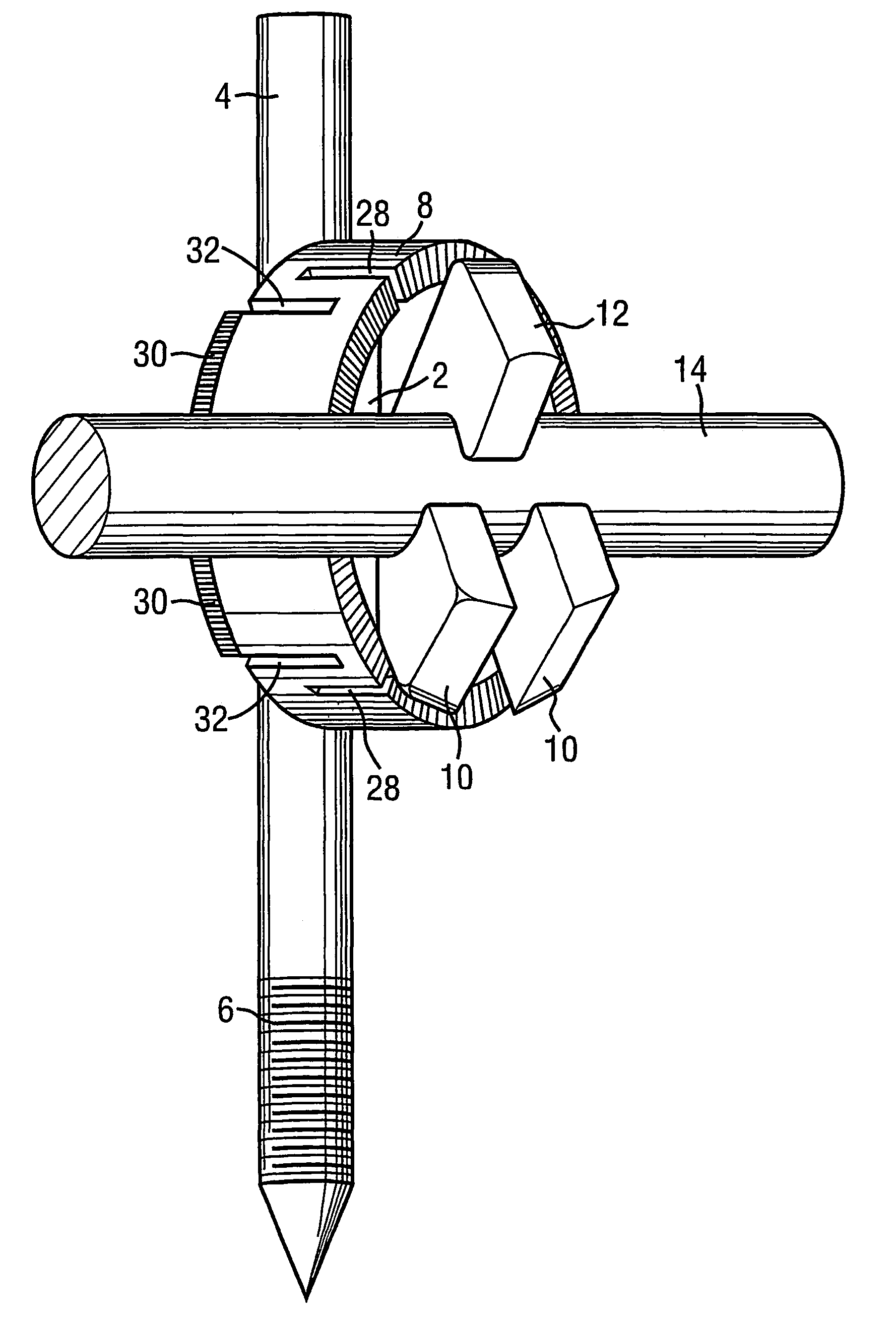
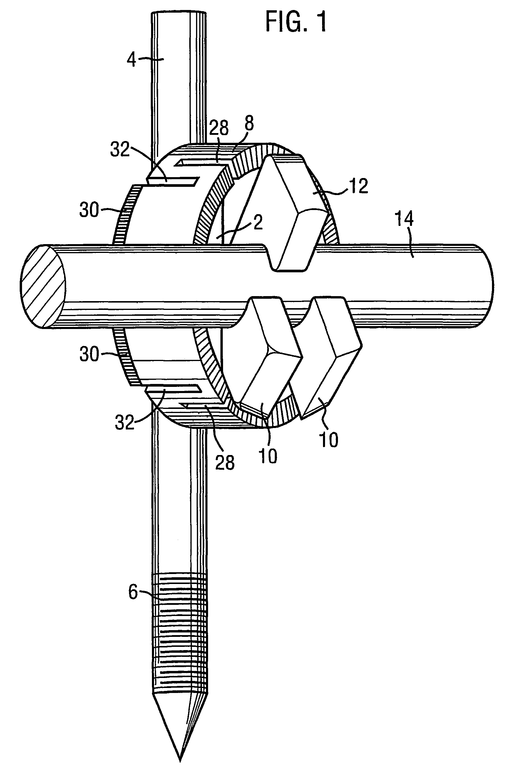
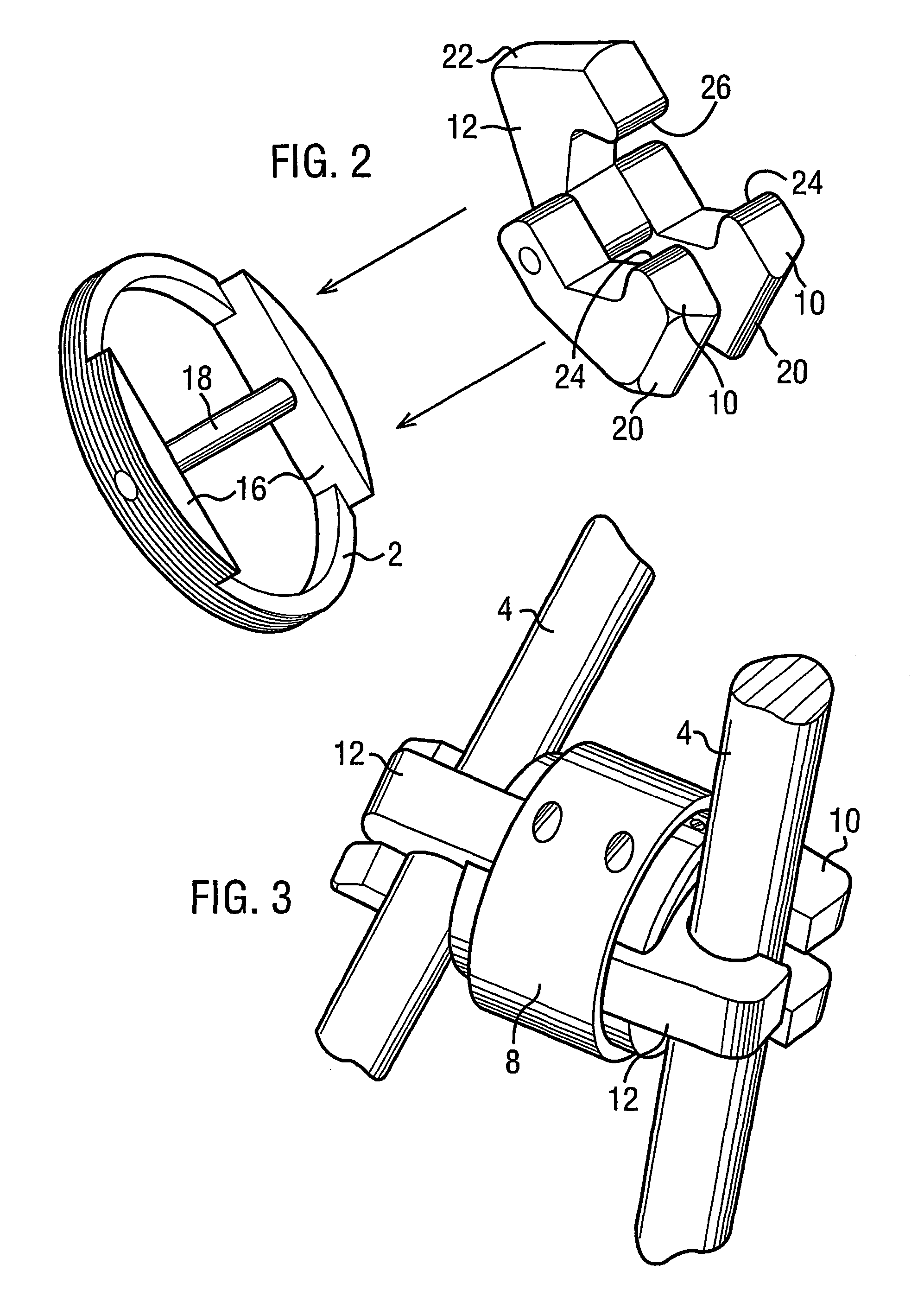
[0017]In FIG. 1 a support body 2 is fixedly mounted on shaft 4 which, as shown, is sharpened at one end and formed with a threaded section 6. Such a shaft might be a cortical bone screw forming part of an external fixation mechanism in a surgical repair. The support body 2 is enclosed within a sleeve 8 from which apparently project gripping elements 10 and 12, to hold a rod 14. The assembly of the support body, sleeve and gripping elements will be readily apparent from FIG. 2.

[0018]The support body shown in FIG. 2 is essentially an annulus with diametrically opposed enlarged sections 16 between which extends a pivot axle 18. Gripping elements 10 and 12 are mounted on the pivot axle 18. When mounted on the pivot axle, lever arms 20 and 22 project beyond the lateral boundary of the support body. The support body 2 is formed with peripheral serrations or teeth, and complementary serrations or teeth are formed on the internal surface of the sleeve 8. The sleeve is partially split at spa...


PUM


Abstract

A gripping device comprises a support body (2) within a sleeve (8), with the sleeve being mounted around the body for relative translational movement along a common axis thereof. A plurality of gripping elements (10, 12) are pivotally mounted in the body (2), the elements having lever arms (20, 22) projecting laterally from the boundary of the body. Translational movement of the sleeve (8) relative to the body (2) causes working engagement of the sleeve with the gripping element lever arms (20, 22), and movement of the lever arms to pivot the elements (10, 12) and close the elements around an item captured therebetween. Normally, the pivotal axes for the gripping elements (10, 12) are disposed within the support body (2), with the elements themselves projecting axially from an end thereof. The pivotal axes are normally substantialy parallel, and indeed the gripping elements may all be mounted for pivotal movement about the same common axis (18). The pivotal axis or axes will usually be perpendicular to the common axis of the support body and sleeve, but there may be applications in which a different angular relationship between these axes will be used.

Description

[0001]This Application is a U.S. National filing under §371 of International Application No. PCT / GB01 / 03118, filed 11 Jul. 2001, claiming priority from British Appln. No. 0017068.8, filed 11 Jul. 2000 and British Appln. No. 0025345.0, filed 16 Oct. 2000, now pending (which are hereby incorporated by reference).TECHNICAL FIELD[0002]This invention relates to gripping devices, and has particular use in surgical applications. It is especially useful in applications where bones or bone elements require external fixation in situations where delicate adjustment is needed.[0003]According to the invention, a gripping device comprises a support body within a sleeve, with the sleeve being mounted around the body for relative translational movement along a common axis thereof. A plurality of gripping elements are pivotally mounted in the body, the elements having lever arms projecting laterally from the boundary of the body. Translational movement of the sleeve relative to the body causes worki...

Claims


Application Information

Patent Timeline
IPC IPC(8): F16G11/00A61B17/70
CPCA61B17/7041A61B17/7049Y10T403/7135Y10T403/7105Y10T403/7194Y10T403/7171Y10T403/7129
Inventor VAGN-ERIK, DALL
Owner VAGN ERIK DALL
Why Eureka
Try Eureka