Device for mounting a component such as a pipe on a stud

a technology for mounting devices and components, which is applied in the direction of threaded fasteners, machine supports, other domestic objects, etc., can solve the problems of large insertion force required to insert the studs and weak attachment of the device to the studs, and achieve the effect of minimizing slippag

Inactive Publication Date: 2008-01-22
NEWFREY
View PDF15 Cites 10 Cited by
  • Summary
  • Abstract
  • Description
  • Claims
  • Application Information

AI Technical Summary

Benefits of technology

[0007]The present invention makes use of only a single pawl in a manner that minimizes slippage.
[0008]An object of the present invention is to provide a device for mounting a component on a stud, in which the stud can be inserted into a bore of the device from either end, with a small insertion force, and in which a single pawl provides attachment of the device to the stud that is strong and reliable.

Problems solved by technology

However the fingers are bent nearly 90° from the hinge sections, and as a result a large insertion force is required to insert the stud.
Also, because the retention force is limited by the thin sections, the attachment of the device to the stud is weak.

Method used


Image

  • Device for mounting a component such as a pipe on a stud
  • Device for mounting a component such as a pipe on a stud
  • Device for mounting a component such as a pipe on a stud

Examples


Embodiment Construction

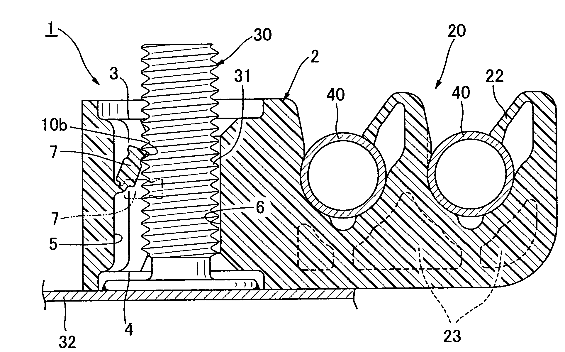
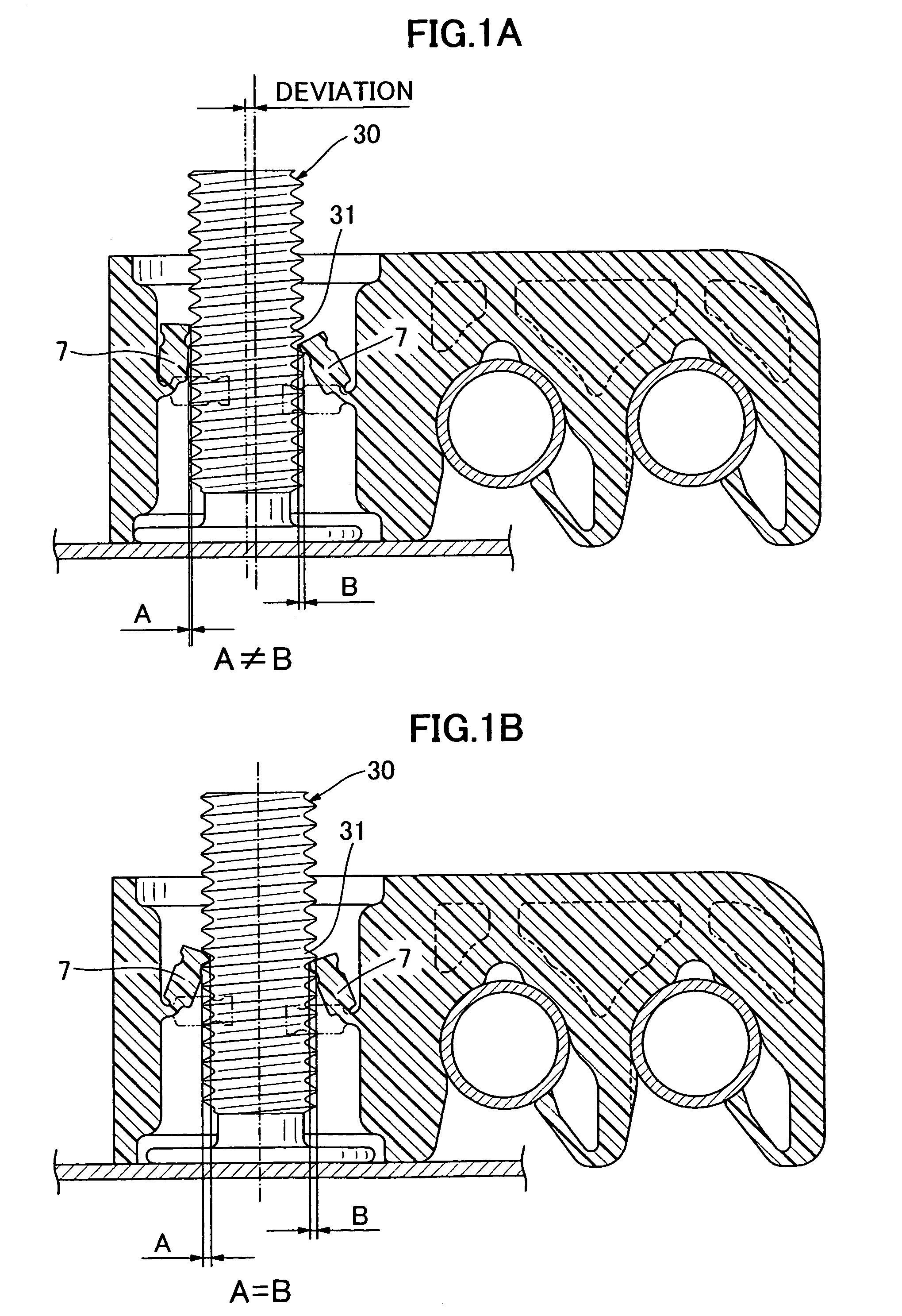
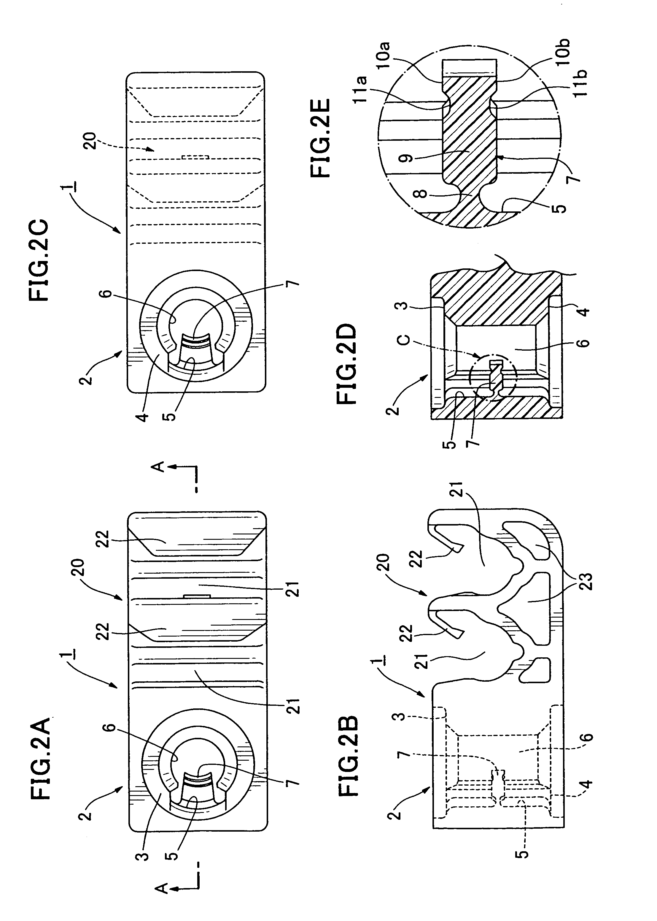
[0021]An embodiment of the invention shown in FIGS. 2A-2E, 3, 5 and 6 of the drawings comprises a device 1 having a main body section 2 and a component mounting section 20 for attaching a component such as a pipe or dash silencer to a threaded stud 30. In the form shown, the upper and lower surfaces of the main body section 2 are nearly flat, and dish shaped recesses 3 and 4 are formed in the upper and lower surfaces to accommodate a widened base of the stud. A bore is formed in the main body section 2. The stud 30 is inserted into the bore from either end to attach the device 1 to the stud.

[0022]A single pawl 7 extends from an inner wall 5 of the bore of the main body section 2 substantially perpendicular to the axis of the bore, as shown in FIGS. 2D and 2E.

[0023]As shown in FIG. 2E, adjacent to the inner wall 5 of the bore, the pawl 7 has a flexible thin section 8 forming a hinge that permits the pawl 7 to bend from the thin section 8 in either axial direction of the bore. The thi...


PUM


Abstract

A device for mounting a component, such as a pipe, on a threaded stud comprises a main body section with a bore for inserting a stud and a component mounting section. The device includes only a single pawl that extends from a first inner wall of the bore in a direction perpendicular to the axis of the bore. The pawl has a flexible thin section connected to the inner wall and a thick section extending from the thin section. The pawl can be bent in opposite directions at the thin section. A pair of thread engaging sections for engaging threads of the stud are formed at an end of the thick section. A pair of grooves for engaging threads are formed adjacent to respective engaging sections.

Description

CROSS-REFERENCE TO RELATED APPLICATIONS[0001]This application is a continuation-in-part of application Ser. No. 10 / 624,646 filed Jul. 23, 2003, now U.S. Pat. No. 7,008,160 issued Mar. 7, 2006, and claims the benefit of Japanese Patent Application No. 2002-272668 filed Sep. 19, 2002, and Japanese Patent Application No. 2002-224620 filed Aug. 1, 2002, both incorporated herein by reference.BACKGROUND OF THE INVENTION[0002]This invention relates to a device for mounting components, such as pipes, on a stud.[0003]Prior devices for attaching a component to a threaded stud, welded to the body of an automobile, for example, have a bore into which the stud is inserted to engage pawls that fasten the device to the stud. In one such device, the orientation of the pawls in the bore is fixed, which restricts insertion of the stud into the bore to a single direction.[0004]Japanese Unexamined Patent Application Publication No. 9-159061 discloses a device for attaching a component to a stud, in whi...

Claims


Application Information

Patent Timeline
Patent Type & Authority Patents(United States)
IPC IPC(8): F16B37/08F16B37/16F16B5/06F16B21/07
CPCF16B5/0685F16B37/0842F16B21/071F16B21/073
Inventor KANIE, HIDEKI
Owner NEWFREY
Why Eureka
Try Eureka