
Hot runner manifold plug for rheological balance in hot runner injection molding

a technology of rheological balance and injection molding, which is applied in the field of injection molding apparatus, can solve the problems of imbalance of flow in the hot runner context, localized elevation of melt temperature, and out-of-spec products from molding machine portions,

Inactive Publication Date: 2008-01-22
MOLD MASTERS 2007
View PDF55 Cites 41 Cited by
  • Summary
  • Abstract
  • Description
  • Claims
  • Application Information

AI Technical Summary

Benefits of technology

[0018]An object of a third aspect of the present invention is to provide an improved injection molding apparatus.

Problems solved by technology

This results in a localized elevation of the temperature of the melt.
This phenomenon can, in some applications, cause preferential flow to some drop locations, and can cause out-of-spec product from portions of a molding machine.
This problem of asymmetric division of shear-heated material has been recognized in a cold runner context; however, it has not been as clearly recognized in a hot runner context.
Instead, imbalance of flow in hot runner context has been attributed to other factors.
Beaumont's device, for example, would not be applicable in a situation in which one of the runners from a downstream split extended out of the plane of the parting line of the mold component.
Many injection molders, however, perform color changes during production runs and cannot tolerate cross-contamination between successive colors.
Static mixers have complex internal structures, and are therefore difficult and time consuming to clean, making them poorly suited to many injection molding applications, such as those where color changes are common and cross-contamination is not tolerated.

Method used


Image

  • Hot runner manifold plug for rheological balance in hot runner injection molding
  • Hot runner manifold plug for rheological balance in hot runner injection molding
  • Hot runner manifold plug for rheological balance in hot runner injection molding

Examples


Embodiment Construction

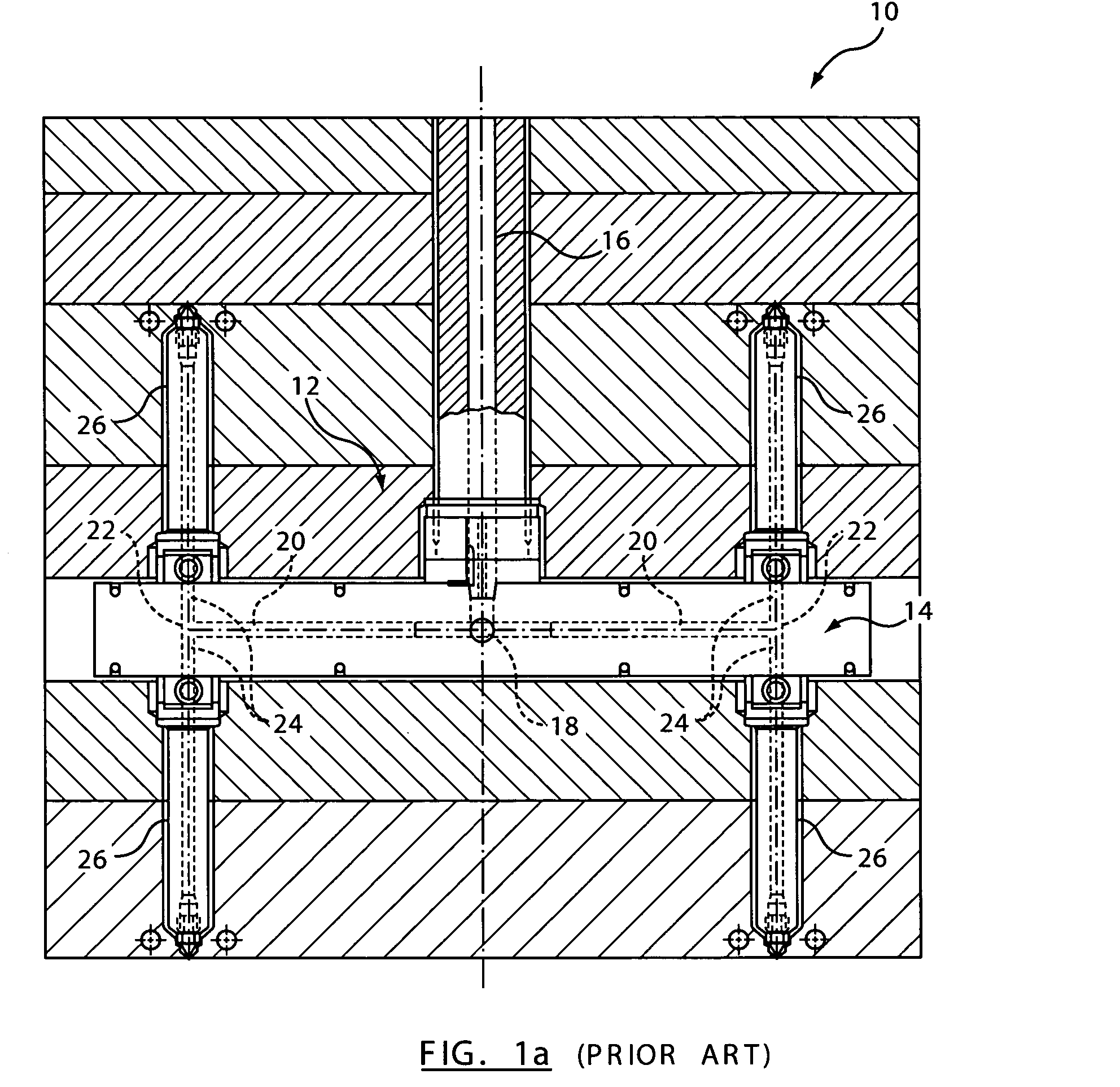
[0055]Referring to FIG. 1a, there is illustrated in a side view, a portion of a stack injection molding apparatus 10 in accordance with the prior art. The stack injection molding apparatus 10 includes a runner system 12 including a manifold 14. The runner system 12 includes a primary runner 16 for receiving melt from a melt source (not shown). At a first branch 18, the primary runner 16 branches into two secondary runners 20. The secondary runners 20, at respective second branches 22, then branch into tertiary runners 24. The tertiary runners 24 supply melt to associated nozzles 26, which inject the melt into associated mold cavities (not shown).

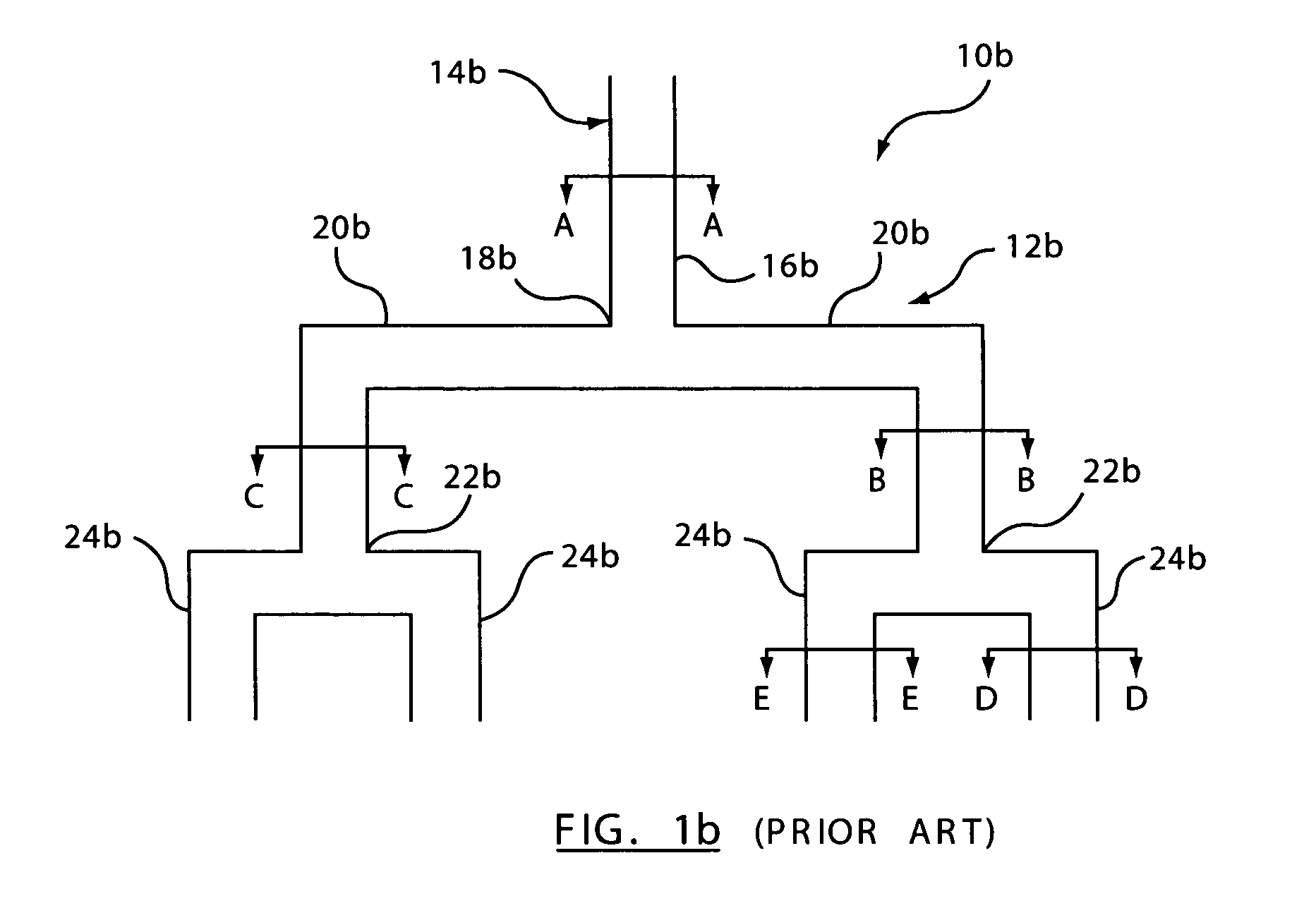
[0056]Referring to FIG. 1b, there is illustrated in a side view, a manifold 14b of an injection molding apparatus 10b in accordance with the prior art. The manifold 14b includes a runner system 12b. The runner system 12b includes a primary runner 16b for receiving melt from a melt source (not shown). At a first branch 18b, the primary runner...


PUM

PropertyMeasurementUnit
meltaaaaaaaaaa
temperatureaaaaaaaaaa
diametersaaaaaaaaaa

Abstract

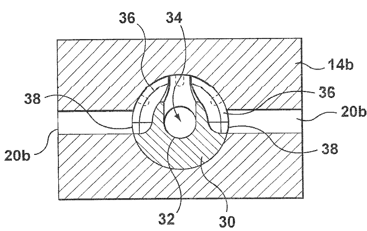
A method and apparatus for rotating a cross-sectional asymmetrical condition of a laminar flowing material is provided in a hot runner system for supplying a laminar flowing material. The hot runner system has (i) an upstream melt passage, (ii) a pair of intermediary melt passages downstream from the upstream melt passage, and (iii) for at least one intermediary melt passage, an associated pair of downstream melt passages downstream from the at least one intermediary melt passage. The cross-sectional asymmetrical condition of a laminar flowing material is rotated by providing a bending path for orienting at least one path outlet relative to a path inlet to rotate the cross-sectional asymmetrical condition of the laminar flowing material such that the cross-sectional asymmetrical condition is substantially equally divided between the two downstream portions.

Description

FIELD OF THE INVENTION[0001]This invention relates to an injection molding apparatus and, more specifically, to a multi-cavity injection molding apparatus that includes a balanced hot runner layout in a stack mold or manifold.BACKGROUND OF THE INVENTION[0002]The use of stack molds and manifolds in a hot runner injection molding apparatus is well known. Furthermore, it is well known that in many applications it is important that a runner layout be provided such that each cavity receives the same flow of melt having the same temperature and the same composition. Balancing of the runner system results in overall higher quality molded parts because consistency is achieved from mold cavity to mold cavity in a multi-cavity application. Even in multi-runner, single cavity applications, the benefits of balancing are well known and important.[0003]A well-known technique for balancing a manifold or stack mold is to match runner diameters and lengths and to match the number of turns in the run...

Claims


Application Information

Patent Timeline
Patent Type & Authority Patents(United States)
IPC IPC(8): B29C45/00B29C45/27B29C45/30B29C45/32
CPCB29C45/2725B29C45/30B29C45/2737B29C45/322B29C2045/308
Inventor BABIN, DENISCOLONICO, GINO
Owner MOLD MASTERS 2007
Learn More