Optical cable

a technology of optical fibers and optical fibers, applied in the field of optical cables, can solve the problems of increasing micro-bending loss, and achieve the effects of suppressing the increase of transmission loss in the coating of optical fibers, reducing the outer diameter of the cable, and improving the contained efficiency of the coated optical fibers

Active Publication Date: 2008-01-22
SUMITOMO ELECTRIC IND LTD +1
View PDF5 Cites 41 Cited by
  • Summary
  • Abstract
  • Description
  • Claims
  • Application Information

AI Technical Summary

Benefits of technology

[0011]In accordance with an optical cable of the present invention, reduction of an outer diameter of the cable and / or improvement of contained efficiency of coated optical fibers can be achieved while an increase of transmission loss in the coated optical fibers is suppressed.

Problems solved by technology

A tape-slotted type of optical cable is excellent in contained efficiency of the coated optical fiber; there occurs easily bending in the coated optical fiber during the manufacture or using, which tends to increase micro-bending loss.

Method used


Image

  • Optical cable
  • Optical cable
  • Optical cable

Examples


Embodiment Construction

[0023]In the following, embodiments of the optical cable according to the present invention will be explained in detail with reference to FIGS. 1 to 10. In the explanation of the drawings, the same elements will be denoted by the same reference symbols and these redundant descriptions will be omitted.

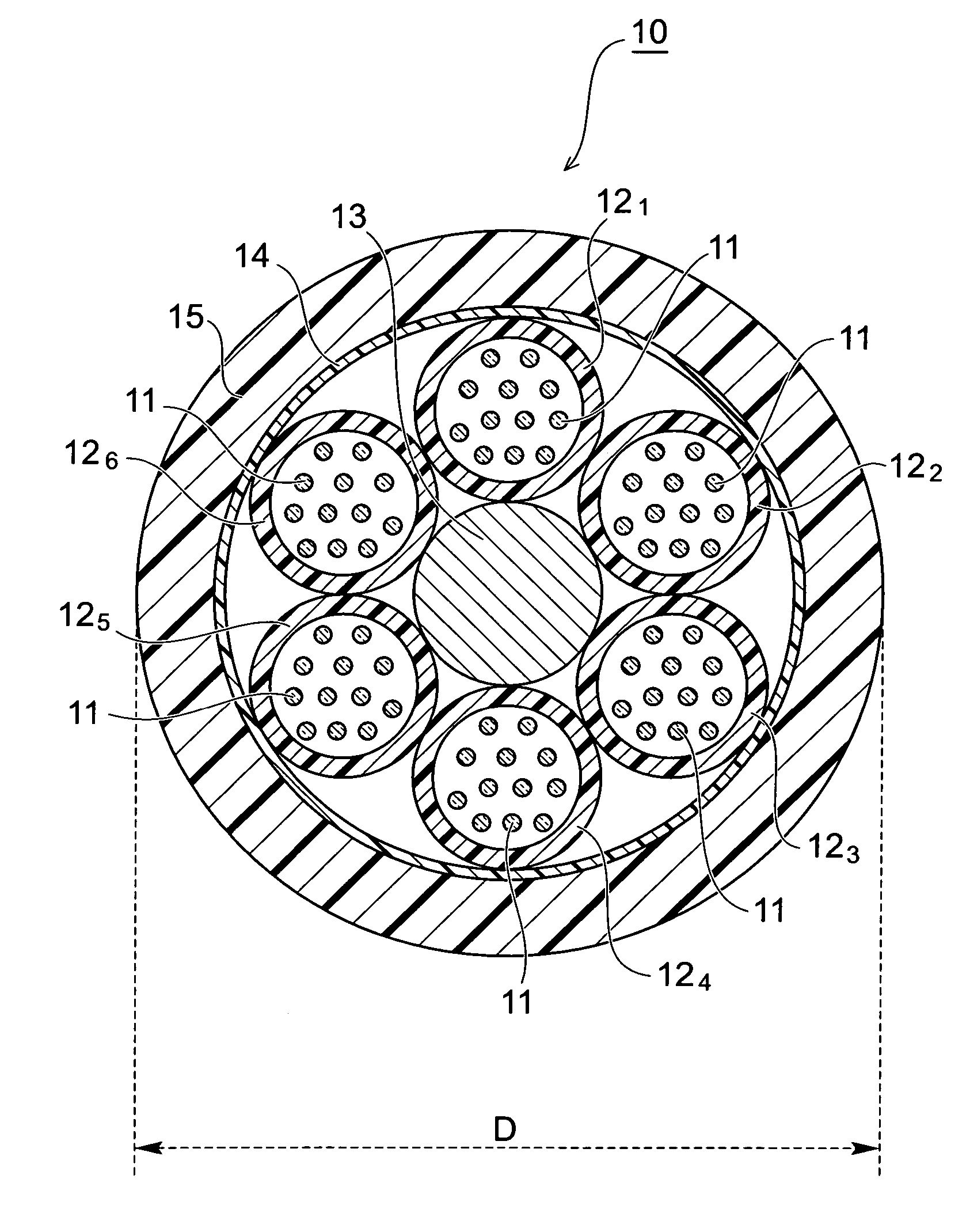
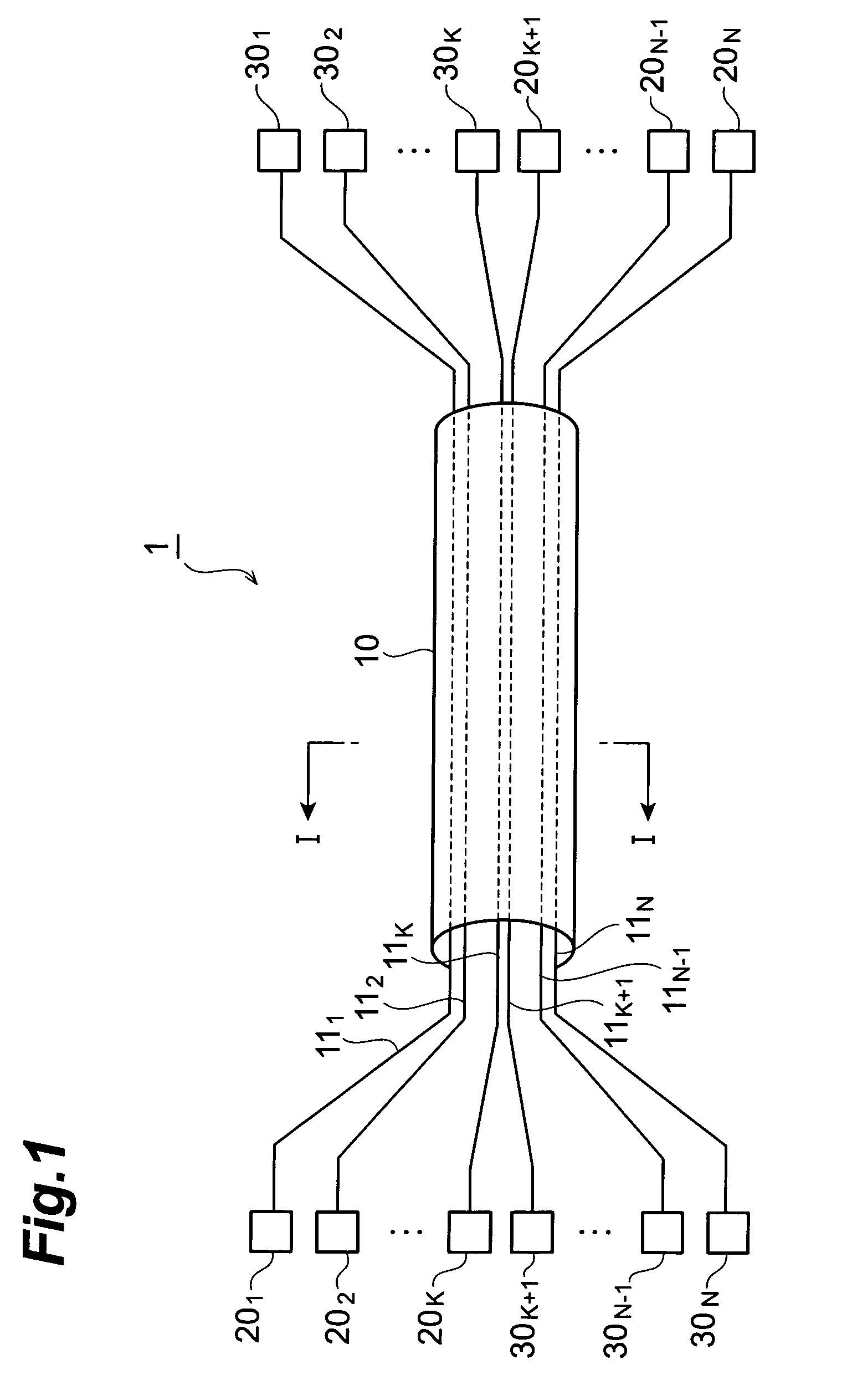
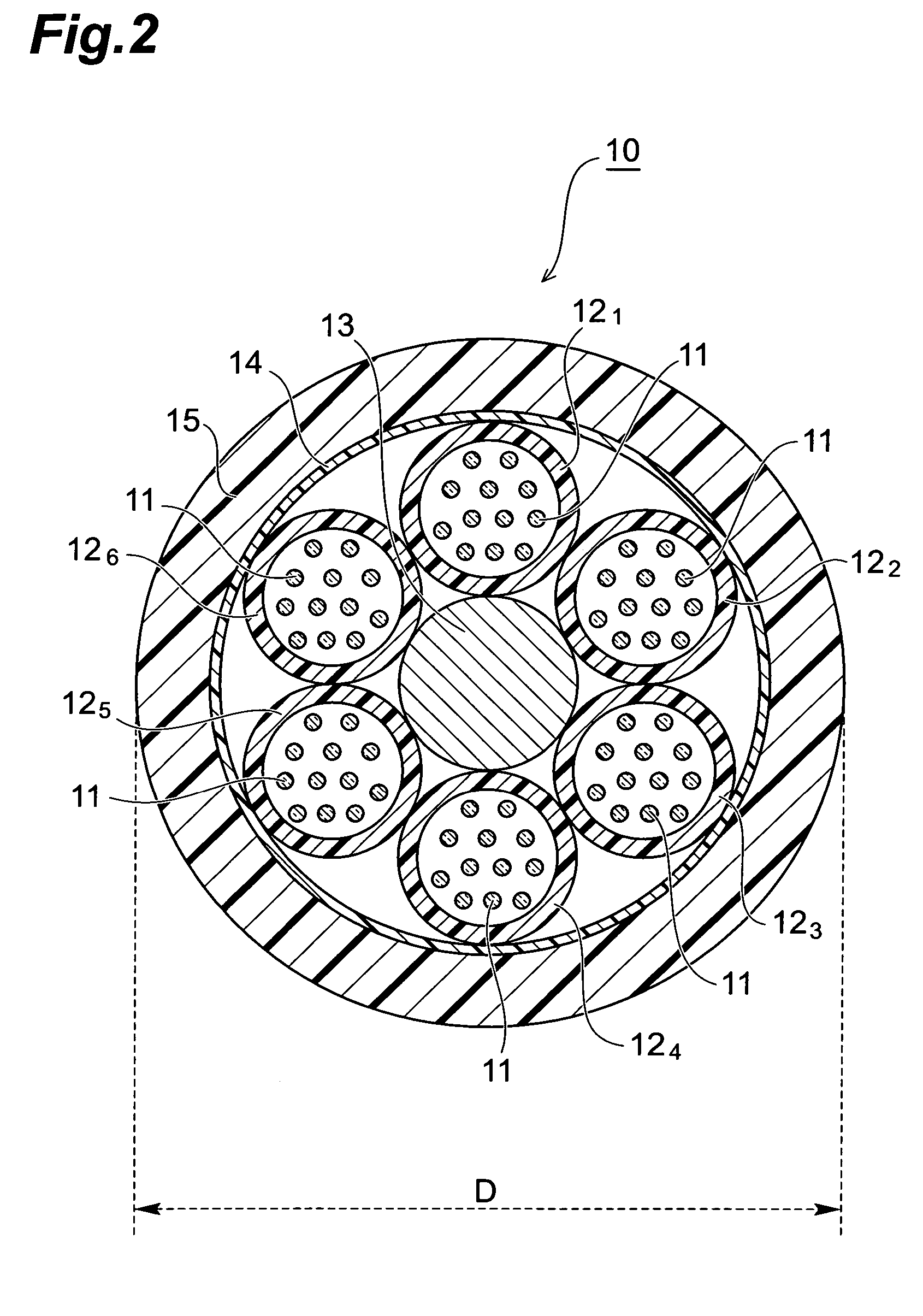
[0024]FIG. 1 is a diagram showing a schematic construction of an optical transmission system in which one embodiment of an optical cable according to the present invention is applied as an optical transmission line. An optical transmission system shown in FIG. 1 composes an optical cable 10, optical transmitters 201 to 20N, and optical receivers 301 to 30N. In the optical cable 10, N optical fibers 111 to 11N (N: an integer of two or more) are bundled. The optical transmitters 201 to 20K and the optical receivers 30K+1 to 30N are arranged on one end side of the optical cable 10, while the optical transmitters 20K+1 to 20N and the optical receivers301 to 30K are arranged on the other end...


PUM


Abstract

An optical cable according to the present invention relates to an optical cable having a construction to enable reduction of a cable outer diameter, and / or improvement of contained efficiency of coated optical fibers while an increase of transmission loss in each coated optical fiber is suppressed. The optical cable has a loose-tube type of structure constructed by: a tension member; a plurality of tubes stranded together around the tension member; and an outer sheath covering the outer periphery of the plurality of tubes. One or more coated optical fibers are contained in each tube. A ratio of A / B is 6.3 or more but 7.0 or less, where each coated optical fiber has a mode field diameter A in a range of 8.6±0.4 μm at a wavelength of 1.31 μm, and where a fiber cutoff wavelength thereof is B μm.

Description

[0001]This application is the U.S. National Phase under 35 U.S.C. § 371 of International Application No. PCT / JP2005 / 020707, filed Nov. 11, 2005, which in turn claims the benefit of Japanese Application No. 2004-327950, filed Nov. 11, 2004, the disclosures of which Applications are incorporated by reference herein in their entirety.TECHNICAL FIELD[0002]The present invention relates to an optical cable constructed by bundling a plurality of optical fibers.BACKGROUND ART[0003]For the structure of an optical cable bundled by a plurality of coated optical fibers, a variety of structures such as tape-slotted type and loose-tube type are known (see Non-Patent Document 1). A tape-slotted type of optical cable is excellent in contained efficiency of the coated optical fiber; there occurs easily bending in the coated optical fiber during the manufacture or using, which tends to increase micro-bending loss. On the other hand, a loose-tube type of optical cable is characterized in that an incre...

Claims


Application Information

Patent Timeline
Patent Type & Authority Patents(United States)
IPC IPC(8): G02B6/44
CPCG02B6/4434G02B6/441
Inventor YOKOKAWA, TOMOYUKISASAOKA, EISUKE
Owner SUMITOMO ELECTRIC IND LTD
Why Eureka
Try Eureka