Suspension for elongated objects, in particular cables

a technology of elongated objects and suspensions, applied in the direction of hose connections, machine supports, other domestic objects, etc., can solve the problems of longer shifts and inability to be shifted, and achieve the effect of simple attachmen

Inactive Publication Date: 2008-01-29
NEWFREY
View PDF24 Cites 37 Cited by
  • Summary
  • Abstract
  • Description
  • Claims
  • Application Information

AI Technical Summary

Benefits of technology

[0006]The object of the invention is to create a suspension of the kind initially mentioned that makes possible a simple arrangement of the suspension on an elongated object and a simple attachment of the elongated object to a support provided for the purpose.
[0008]With the invention, a suspension of the specified kind has been created in which the holder can be connected to the tension band at a plurality of attachment locations, so that for each situation of installation, a suitable attachment location is available. Consequently, no prior orientation of the tension band in circumferential direction is required in the fastening of the tension band to the cable. After installation of the tension band, the holder may either be connected first to the tension band and then to the support, or first to the support and then to the tension band, so that, according to the application, simple possibilities of installation for a cable tree around which the tension band is looped are available. The tension band according to the invention is producible in especially economical manner, as it is not provided with expensive holding means. Tension bands unwound from a roll and cut to length may also be connected to each other to produce the suspension according to the invention. This last is especially advantageous for automatic installation of the tension band.
[0009]An advantageous embodiment of the invention provides that the holder shall comprise at least one finger partly or completely overlapping one end of the tension band on the inside, facing the elongated object. The end of the finger may be opposed to an area of the holder forming a purchase for the outside of the tension band. This conformation has the advantage that conventional tension bands may be used. The clearance required for the finger between tension band and slung object in this embodiment may be produced by a loose installation of the tension band on the object, the tension band requiring as a rule to be tightened after attachment of the holder.
[0011]According to another proposal of the invention, the holder comprises two fingers arranged as mirror images of each other on either side of a support area and having bent finger ends overreaching the tension band from both sides on the inside. This conformation has the advantage that greater holding forces and in particular greater bending moments can be transmitted at the point of connection between holder and tension band. Besides, the tension band can be connected to the holder by a motion directed transverse to the lengthwise extent of the slung object. To facilitate such an assembly operation, provision can be made so that the bent ends of the fingers have end surfaces so inclined that the distance between the end surfaces increases with increasing distance of the end surfaces from the support area. Alternatively or additionally thereto, provision may be made for the tension band to have a trapezoidal cross-section whose wider parallel side is located on the inside of the tension band. By the conformation of the end surfaces of the finger ends and / or the cross-sectional shape of the tension band as described, the finger ends are spread apart when the tension band is pressed against the holder, so that they slip away over the side surfaces of the tension band and finally embrace the tension band on the inside.

Problems solved by technology

If this known suspension is to be employed in producing prefabricated cable trees, then there is the problem that the suspension must be arranged in an exactly defined angular position on the cable tree, since a subsequent rotation of the suspension into the correct position of installation relative to the cable tree is no longer feasible, or only with difficulty.
This is an impediment both to production of the cable tree and to installation of the cable tree, especially when the latter must moreover be thrust through openings in the bodywork.
In the case of this suspension also, there is the problem that the tension band, when arranged on the cable tree, must be brought into a well-defined position of angular rotation, since after its installation, the tension band can no longer be shifted relative to the cable tree.

Method used


Image

  • Suspension for elongated objects, in particular cables
  • Suspension for elongated objects, in particular cables
  • Suspension for elongated objects, in particular cables

Examples


Embodiment Construction

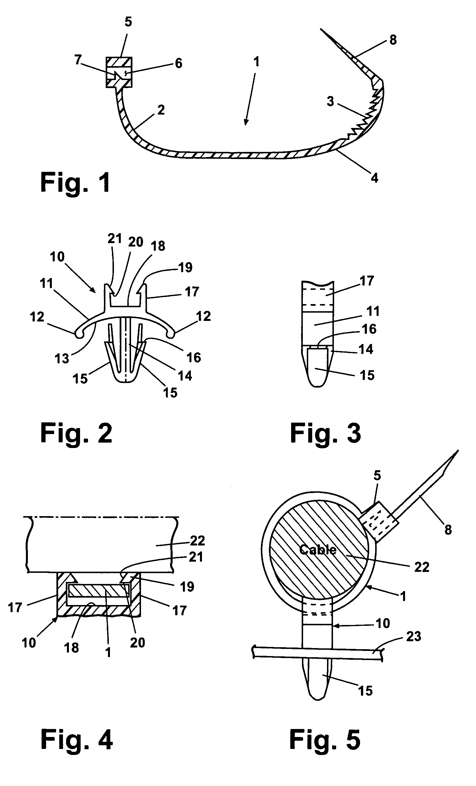
[0027]FIG. 1 shows a tension band 1 of conventional conformation, suitable for formation of the suspension according to the invention. The tension band 1 consists of a flexible strip of rectangular cross-section, and is made of a tension-resistant, in particular synthetic, material. On its inner side 2 capable of being looped around the objects to be held, the tension band 1 comprises, at least over a portion of its length, a saw-like toothing 3. The outside 4 of the tension band 1 is smooth. At its one end, the tension band 1 comprises a lock 5 having an opening 6. In the opening 6, a locking tooth 7 is arranged. The opposed end 8 of the tension band 1 is tapered to a point to facilitate insertion in the lock 5.

[0028]For attachment to a cable, for example, the tension band 1 is placed around the cable, and then the end 8 is passed through the opening 6 of the lock 5. By the end 8 protruding from the opening 6, the tension band end 1 is then drawn through the lock 5 until it closes ...


PUM


Abstract

In a suspension for elongated objects, in particular cables (22) or the like, having a tension band (1) formable into a ring encircling the object and held together by a closure, and having a holder (30) separate from the tension band (1) for attachment of the tension band (1) to a support, the holder (30) comprises a finger (37) one end (39) of which overreaches the tension band (1) on the inside facing the cable (22). The end (39) of the finger (37) is opposed to an area of the holder (30) having a spring element (44) in contact with the outside of the tension band (1). A lock (42) secures the finger (37) in its position of engagement. After installation of the tension band (1), the holder (30) may be attached to the tension band (1) in a plurality of locations.

Description

CROSS-REFERENCE TO RELATED APPLICATIONS[0001]This application claims the benefit of German Patent Application No. 103 49 046.9, filed Oct. 17, 2003. The disclosure of the above application is incorporated herein by reference.FIELD OF THE INVENTION[0002]The invention relates to a suspension for elongated objects, in particular cables or the like, having a tension band formable into a ring looped around the object and held together by a closure, and having a holder separate from the tension band for attaching the band to a support.BACKGROUND OF THE INVENTION[0003]Suspensions of the kind specified are suitable chiefly for attaching cable trees in vehicles. Today's vehicles contain numerous electrical components. These components must be supplied with electrical energy, and many of these components have interrelated functions and must therefore be connected to each other. For these reasons, extensive electric cablings are required in vehicles, combined in cable trees and then installed ...

Claims


Application Information

Patent Timeline
Patent Type & Authority Patents(United States)
IPC IPC(8): F16L3/08B65D63/12B65D63/14F16L3/137F16L3/233H02G3/30
CPCF16L3/137F16L3/233Y10T24/1498
Inventor MIELKE, KARL-HEINZWIMMER, KARINZOLTNER, KLAUSSCHMIDT, MICHAEL
Owner NEWFREY
Why Eureka
Try Eureka