Frame structure for working vehicle

a working vehicle and frame technology, applied in the direction of roofs, tractors, transportation and packaging, etc., can solve the problems of increasing weight and solving problems, and achieve the effect of improving the rigidity of the frame, improving the intensity of the frame of the working vehicle, and efficient reinforcement of high rigidity

Inactive Publication Date: 2010-11-16
YANMAR CO LTD
View PDF13 Cites 25 Cited by
  • Summary
  • Abstract
  • Description
  • Claims
  • Application Information

AI Technical Summary

Benefits of technology

[0023]According to the frame structure for the working vehicle of the present invention, rigidity of the frame is improved so that intensity of the frame of the working vehicle is improved. Parts requiring high rigidity are reinforced efficiently. The frame is reinforced efficiently with easy construction.
[0024]According to the frame structure for the working vehicle of the present invention, rigidity of the mast section is improved so that intensity of the frame of the working vehicle is improved. The frame of the working vehicle is rigid enough to bear when a working machine such as a backhoe is attached to the rear portion of the frame. The part requiring high rigidity is reinforced efficiently so as to make the mast section supporting a front loader light and having high load capacity. The inner side of the mast is circular arc-shaped so as to lighten stress.
[0025]According to the frame structure for the working vehicle of the present invention, support rigidity of the radiator mount is improved so that silence of an engine room is improved. Cost is reduced, and space in the engine room is saved.
[0026]According to the frame structure for the working vehicle of the present invention, bolts for attachment of the rear transaxle are screwed easily so that assembly workability of the working vehicle is improved. Attachment of the rear transaxle is simplified, and excessive load to the rear transaxle and the frame of the working vehicle is suppressed by transformation of the plate body.
[0027]According to the frame structure for the working vehicle of the present invention, attachment of the transmission is simplified, and excessive load to the frame of the working vehicle is suppressed by transformation of the plate body.
[0028]According to the frame structure for the working vehicle of the present invention, the number of parts of the working vehicle is reduced so as to improve workability of assembly process.

Problems solved by technology

Further, attaching of many members increases weight.
These are also problems to be solved.

Method used


Image

  • Frame structure for working vehicle
  • Frame structure for working vehicle
  • Frame structure for working vehicle

Examples


Embodiment Construction

[0056]The present invention provides a light and rigid frame of a working vehicle by using a reinforcement member.

[Entire Construction]

[0057]Explanation will be given to a working vehicle that is an embodiment of the present invention.

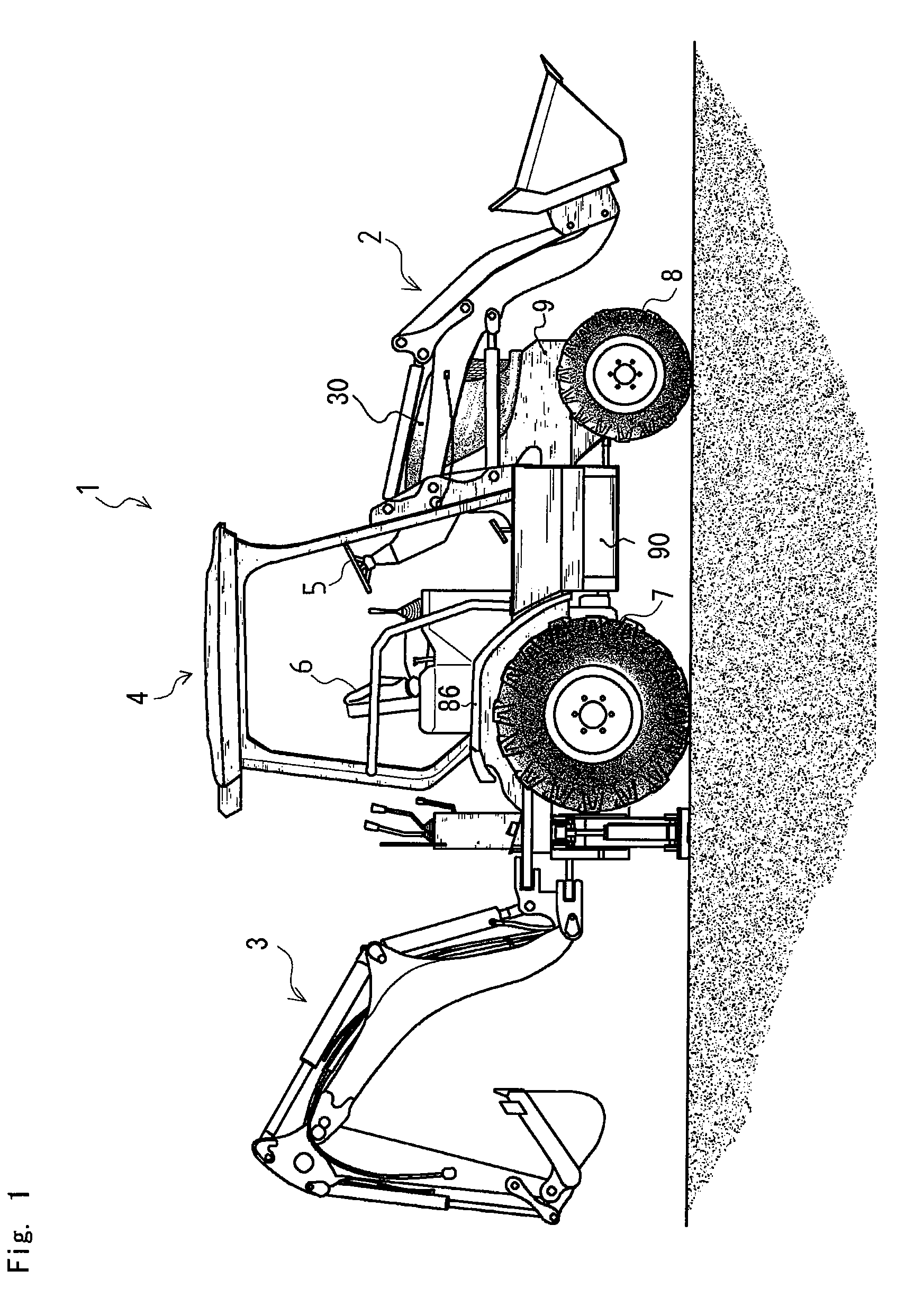
[0058]FIG. 1 is an entire side view of the working vehicle.

[0059]The working vehicle 1 is a tractor loader backhoe and is equipped with a loader 2 and an excavator 3. An operation part 4 is provided at the center of the working vehicle 1. The loader 2 is disposed before the operation part 4 and the excavator 3 is disposed behind the operation part 4. The working vehicle 1 is equipped with front wheels 8 and rear wheels 7 so as to travel while equipped with the loader 2 and the excavator 3.

[0060]A steering wheel 5 and a seat 6 are disposed in the operation part 4, and a traveling operating device and an operating device of the loader 2 are disposed at the side of the seat 6. Accordingly, steering operation of the working vehicle 1 and the operation of t...


PUM


Abstract

Rigidity of a frame of a working vehicle is improved by a simple structure and production costs are reduced by reducing the number of parts of a working vehicle. Pipes 66 are provided on both left and right sides at the center in the front-rear direction of a side frame 62, and each pipe 66 has a rectangular cross-section and penetrates an intermediate partition in the front-rear direction from a mast section 64 up to a transmission section. Tie-down holes are formed in a front face plate 61 to which the front end of a frame 9 is connected, and a plate 64b connected to a side frame 62 is provided at the bottom surface of each mast section 64 protruding outward from the side frame 62. Tanks installed on the working vehicle are suspended from the plate bodies 64b, and a lift arm installation boss provided at each mast section 64 is supported at both ends. A U-shaped reinforcement member 81 connects the upper surface of mast partition plate of a mast section 64 and left and right bosses.

Description

BACKGROUND OF THE INVENTION[0001]1. Field of the Invention[0002]The present invention relates to a frame structure for a working vehicle. In more detail, the present invention relates to an easy and cheap construction of light and rigid frame of a working vehicle.[0003]2. Background Art[0004]Conventionally, there is well known a frame of a working vehicle constructed by square pipes, I-shaped steel and the like. The frame of the working vehicle is constructed by I-shaped steel and the like, and various devices are attached to the frame as needed (for example, see the Patent Literature 1).[0005]A frame mainly comprising square pipes and I-shaped steel is difficult to be processed so as to require prodigious labor for assembly. Furthermore, high cost is required for production.Patent Literature 1: the Japanese Patent Laid Open Gazette 2004-1769BRIEF SUMMARY OF THE INVENTIONProblems to Be Solved by the Invention[0006]The purpose of the present invention is to improve the rigidity of a ...

Claims


Application Information

Patent Timeline
Patent Type & Authority Patents(United States)
IPC IPC(8): B62D21/02B60K17/00
CPCB62D21/186E02F9/0808
Inventor SAKAMOTO, KUNIHIKOTAKATA, KOUICHIOGATA, NAGAHIROYAMASHITA, YOUSUKETAJIMA, MAKIKOAYABE, HIROAKI
Owner YANMAR CO LTD
Why Eureka
Try Eureka