
Curtain-shield airbag clip and assemblies using the clip

a technology of airbag clips and shields, applied in the field of clips, can solve the problems of large reactive force of devices, easy detachment, and simplify automobile assembly operations, and achieve the effects of avoiding or overcoming deficiencies, simple provisional attachment, and high attachment strength

Active Publication Date: 2007-09-25
NEWFREY +1
View PDF19 Cites 26 Cited by
  • Summary
  • Abstract
  • Description
  • Claims
  • Application Information

AI Technical Summary

Benefits of technology

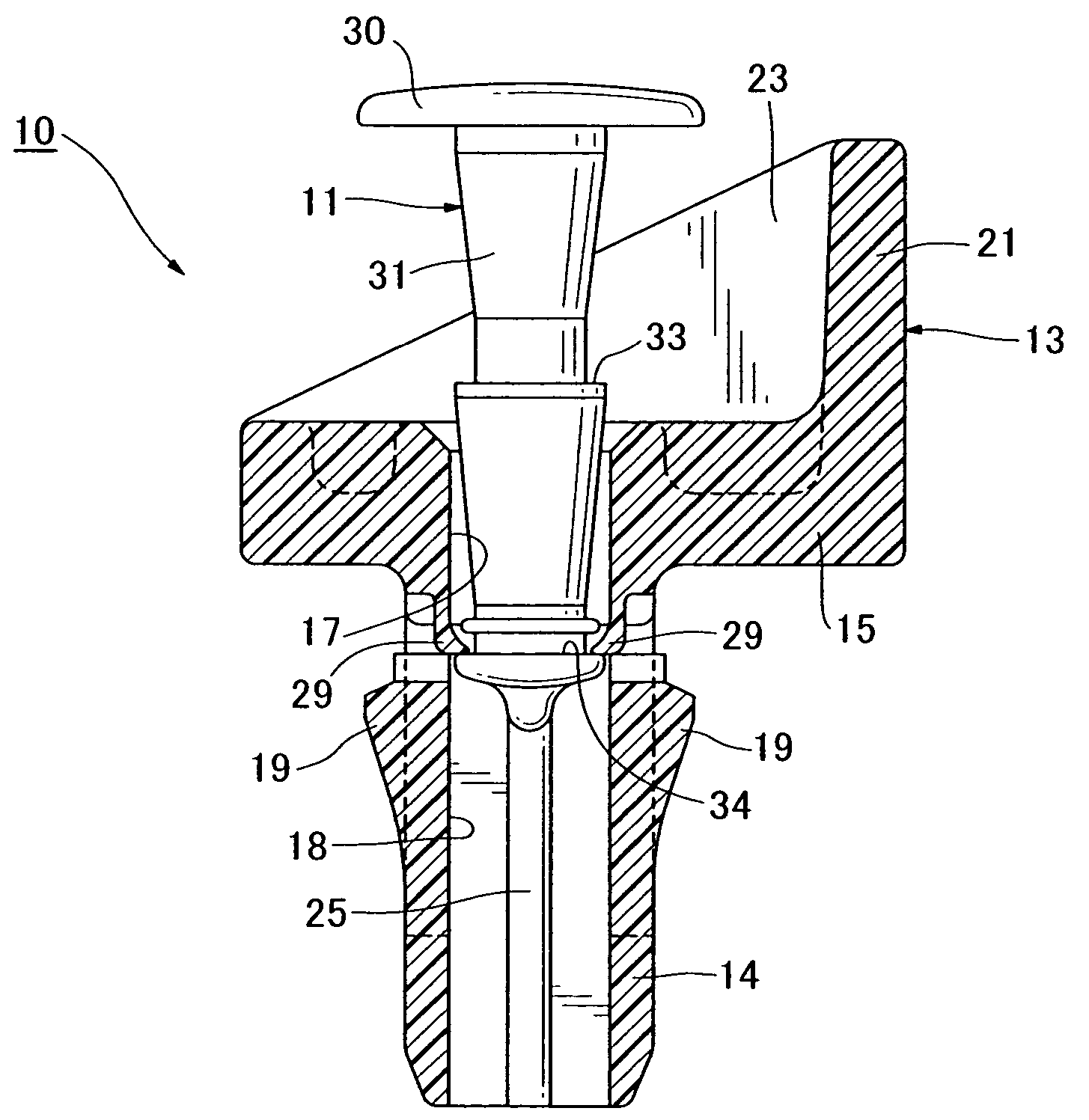
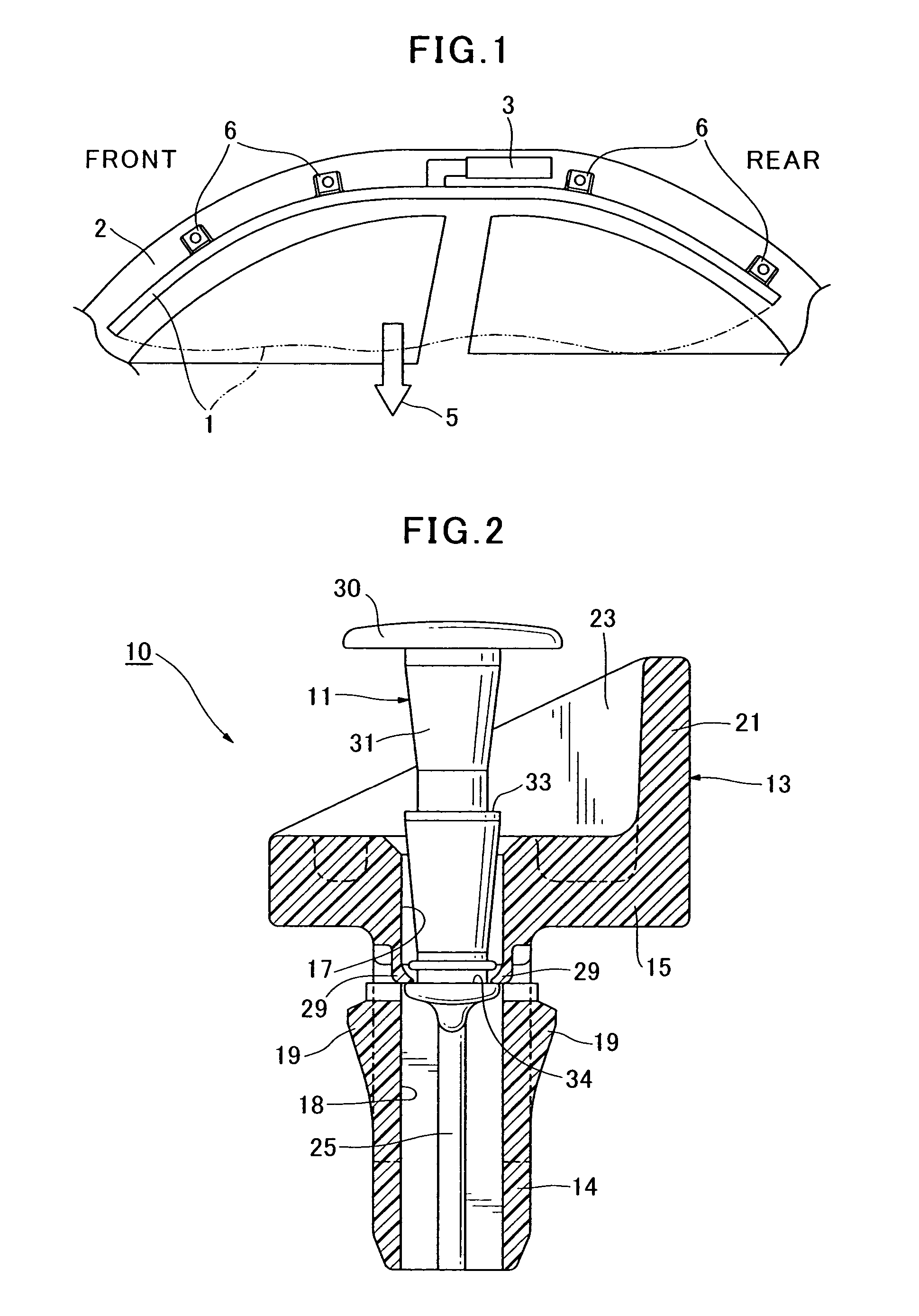
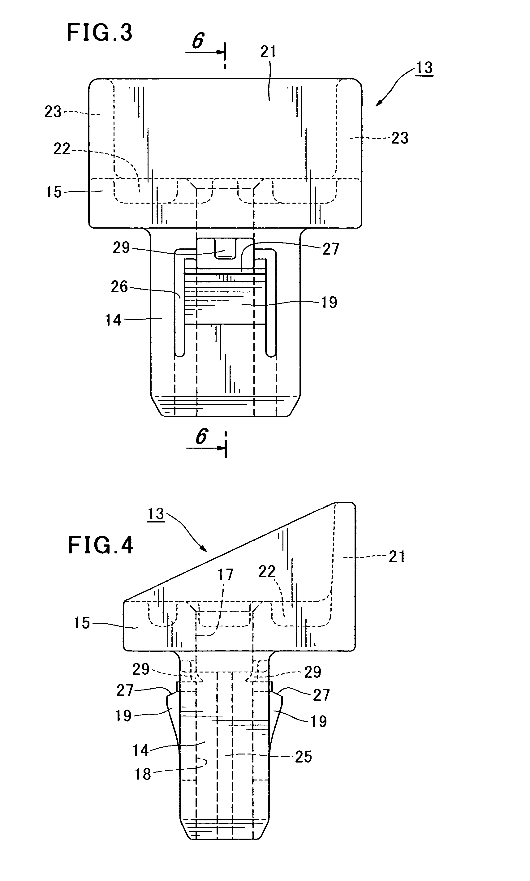
The present invention provides a curtain-shield airbag attachment clip that has high attachment strength, avoids the need for welding a nut to a body panel, provides for simple provisional attachment, avoids the need for installing a tapping screw, and has other advantages. The clip has two components, namely, a pin and a bushing for receiving the pin. The bushing has a bore extending from an opening in the flange and into the leg for receiving the pin therein. The pin can be inserted into the bore of the bushing to be held at a provisional position, at which the engagement piece is able to flex inwardly of the bore in the leg, and a final position at which the engagement piece is prevented from flexing inwardly of the bore. The flange has an integral partition plate which forms a partition between the main airbag unit of the curtain-shield airbag and part of the flange at which the bore opening is located.

Problems solved by technology

Since the airbag deploys very rapidly when activated, the reactive force on the device is large, and there is a danger of detachment.
The strength of that attachment is great, but there is the necessity of welding the nut to the body panel, which militates against simplifying automobile assembly operations.
More particularly, there is no teaching as to how to cope with the reaction force against the clip which accompanies the rapid deployment of the airbag when activated.

Method used


Image

  • Curtain-shield airbag clip and assemblies using the clip
  • Curtain-shield airbag clip and assemblies using the clip
  • Curtain-shield airbag clip and assemblies using the clip

Examples


Embodiment Construction

[0025]A first embodiment of the present invention will now described with reference to the drawings. FIG. 1 basically diagrams how a curtain-shield airbag 1 is attached in an automobile. The curtain-shield airbag 1, which is primarily for protecting the heads of occupants of the automobile, is attached to a body panel 2 at the top of the door windows, from the front to the rear, on the inside of the automobile. At the time of a collision, for example, gas from a compressed gas source 3 (an inflator) is ejected, and the curtain-shield airbag very rapidly deploys toward the lower part of the door windows (in the direction of arrow 5) to protect the heads and other body portions of vehicle occupants. The curtain-shield airbag 1 comprises a main airbag unit and airbag attaching members 6. The airbag attaching members are secured to a body panel, such as a frame of the automobile, at a plurality of prescribed positions at the top of the door windows. The main airbag unit, at normal times...


PUM


Abstract

A clip for attaching a curtain-shield airbag to a body panel of a vehicle comprises a bushing and a pin. The bushing has a flange with a leg extending therefrom. A bore extends through the flange and into the leg for receiving the pin. Outer surfaces of the leg have engagement pieces with shoulders for coupling the bushing to edge regions of a body panel hole into which the leg is inserted. The pin and the bushing are capable of being coupled in a provisionally fixed condition or a permanently fixed condition. When the pin is partially inserted into the bore, the engagement pieces are permitted to flex inwardly of the bore, but when the pin is fully inserted, such inward flexing is prevented. The flange has a wall that provides a partition between the main airbag unit and the entrance hole of the bore in the flange.

Description

CROSS-REFERENCE TO RELATED APPLICATION[0001]This application claims the benefit of Japanese Patent Application No. 2003-204506 filed Jul. 31, 2003, incorporated herein by reference.BACKGROUND OF THE INVENTION[0002]The present invention relates to a clip for attaching an airbag attaching member for a curtain-shield airbag to a body panel and to assemblies using the clip.[0003]A device for attaching a head-protecting curtain-shield airbag to a body panel is disclosed in Laid-Open Patent Application [TOKKAI] No. 2002-104127, gazette publication (Patent Literature 1). This device comprises, a knob, a leg, and an engagement member. By inserting the engagement member and leg of the device into an attachment hole in an airbag attaching member and into an attachment hole in the body panel, and turning the knob, the curtain-shield airbag is attached to the body panel.[0004]A screw grommet for coupling two panels is disclosed in Laid-Open Patent Application [TOKKAI] No. H1-216109 / 1989, gazett...

Claims


Application Information

Patent Timeline
Patent Type & Authority Patents(United States)
IPC IPC(8): B60R21/16B60R21/213B60R21/20F16B19/00F16B19/10
CPCB60R21/213F16B19/1081B60R21/232F16B21/071
Inventor KAWAI, YASUHIROKUBOTA, YASUSHIGOTO, TATSUYANIIMI, HIROKAZU
Owner NEWFREY
Learn More