Hydraulic unit for a vehicle brake system

a technology for vehicle brakes and hydraulic units, which is applied in the direction of braking systems, valve housings, mechanical equipment, etc., can solve the problems of moisture penetration under the hood, not always sealing off reliably and for the entire service life,

Inactive Publication Date: 2000-04-11
ROBERT BOSCH GMBH
View PDF4 Cites 28 Cited by
  • Summary
  • Abstract
  • Description
  • Claims
  • Application Information

AI Technical Summary

Problems solved by technology

A disadvantage of the known hydraulic units is that they do not always seal off reliably and for the entire service life.
Infiltration of the seal from corrosion can lead to the penetration of moisture under the covering hood.
Moreover, relative motions between the covering hood and the hydraulic block because of the extreme temperatures that occur in an engine compartment of a motor vehicle, which can range between -40.degree. C. and +120.degree. C., can lead to leakage.

Method used


Image

  • Hydraulic unit for a vehicle brake system
  • Hydraulic unit for a vehicle brake system
  • Hydraulic unit for a vehicle brake system

Examples


Embodiment Construction

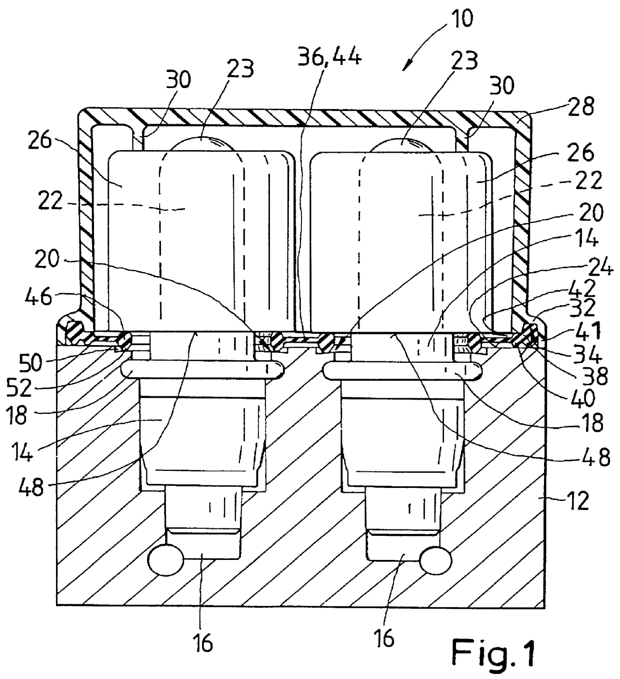
The hydraulic unit 10 according to the invention and shown in FIG. 1 has a hydraulic block 12, in which a total of eight magnet valves 14 are placed side by side in two rows. The magnet valves 14 are inserted into stepped bores 16 of the hydraulic block 12. They have a flange 18, by which they are retained by caulking 20 of material of the hydraulic block 12.

An actuating part 22 of the magnet valves 14 protrudes with a 23 portion extending from the hydraulic block 12 on one side 24. A hollow-cylindrical coil 26 for magnetic valve actuation is slipped onto the actuating part 22.

A covering hood 28 is mounted on the side 24 of the hydraulic block 12 from which the actuating part 22 of the magnet valves 14 protrudes. The covering hood 28 is a plastic injection molded part that covers the magnet valves 14. Retaining struts 30 that are integral with the covering hood 28 press on the inside of the hood in the axial direction against the coils 26 and retain them on the valve dome 23 that co...


PUM


Abstract

PCT No. PCT/DE96/01237 Sec. 371 Date Mar. 23, 1998 Sec. 102(e) Date Mar. 23, 1998 PCT Filed Jul. 9, 1996 PCT Pub. No. WO97/10979 PCT Pub. Date Mar. 27, 1997The invention relates to a hydraulic unit having an hydraulic block, with magnet valves inserted in apertures therein. The magnet valves include protruding valve domes on which coils are mounted. The magnet valves and coils are covered by a covering hood. For sealing purposes, a platelike sealing element, includes a beadlike edge which forms an outer sealing body. The outer sealing body rests between an edge of the covering hood and the hydraulic block, and includes inner bead-like sealing bodies, which rest between the coils of the magnet valves and the hydraulic block. The inner bead-like sealing bodies are integral, via a diaphragm or the like, with the outer sealing body. The sealing body includes a multiple sealing at the edge of the covering hood and individual sealing of each magnet valve. In addition, the inner sealing bodies act as spring elements, which press the coils against retaining struts in the interior of the covering hood and thereby fixes the coils on the valve dome.

Description

PRIOR ARTThe invention is based on a hydraulic unit for a vehicle brake system. Such hydraulic units are used in vehicle brake systems that in particular have an anti-locking or traction control system. Magnet valves are built into a hydraulic block of the hydraulic unit; in the hydraulic block, they are hydraulically connected to the brake system, and their magnetic actuating part protrudes from the hydraulic block on one side. A coil for valve actuation is slipped into the actuating part. The actuating part of the magnet valves is located under a covering hood that retains the coils on the actuating parts. To guard against the entry of dirt or water, a seal may be placed between one edge of the covering hood and the hydraulic block.A hydraulic unit known from German Patent Disclosure DE 41 33 641 A1 has an elastic shaped body, which is placed into the covering hood or cast there, and which receives the coils of the magnet valves. The elastic shaped body has an encompassing sealing...

Claims


Application Information

Patent Timeline
Patent Type & Authority Patents(United States)
IPC IPC(8): B60T8/36F15B13/00F15B13/08F16F15/10F16J15/02F16K27/00
CPCB60T8/3675F15B13/0821F15B13/0814B60T8/36
Inventor MUELLER, KLAUSSCHURR, VOLKER
Owner ROBERT BOSCH GMBH
Why Eureka
Try Eureka