Liquid-cooling heat dissipation apparatus

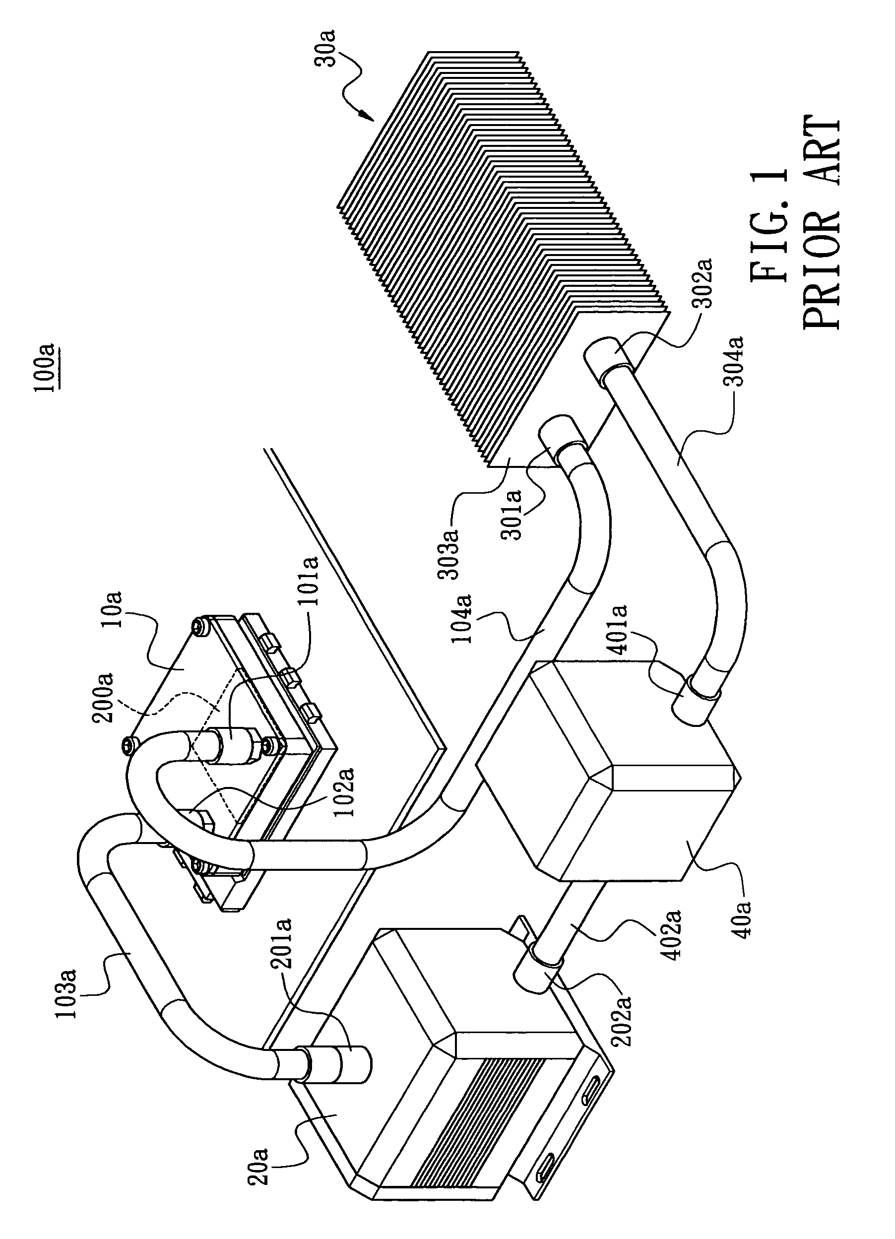
a heat dissipation apparatus and liquid cooling technology, applied in the direction of indirect heat exchangers, light and heating apparatus, air heaters, etc., can solve the problems of i>a /i>thus formed being bulky and difficult to assemble, and affecting the compact trend of computers, etc., to achieve the effect of compact spa

Active Publication Date: 2008-02-05
CHEMTRON RES
View PDF14 Cites 49 Cited by
  • Summary
  • Abstract
  • Description
  • Claims
  • Application Information

AI Technical Summary

Benefits of technology

[0007]The present invention provides a liquid-cooling heat dissipation apparatus with such mechanical design that the liquid driving unit and the cooling plate module can be advantageously integrated into the casing while the duct is reduced to achieve compact space.
[0008]Moreover, the present invention provides a liquid-cooling heat dissipation apparatus with overall structure achieves liquid storing, circulating and heat conveying function.

Problems solved by technology

Beside performance issue, the product appearance, the construction and motherboard connection ways are also under extensive exploited.
The liquid-cooling heat dissipation system 100a thus formed is bulky and hard to assemble.
This is adverse to the compact trend of computer.

Method used


Image

  • Liquid-cooling heat dissipation apparatus
  • Liquid-cooling heat dissipation apparatus
  • Liquid-cooling heat dissipation apparatus

Examples


Embodiment Construction

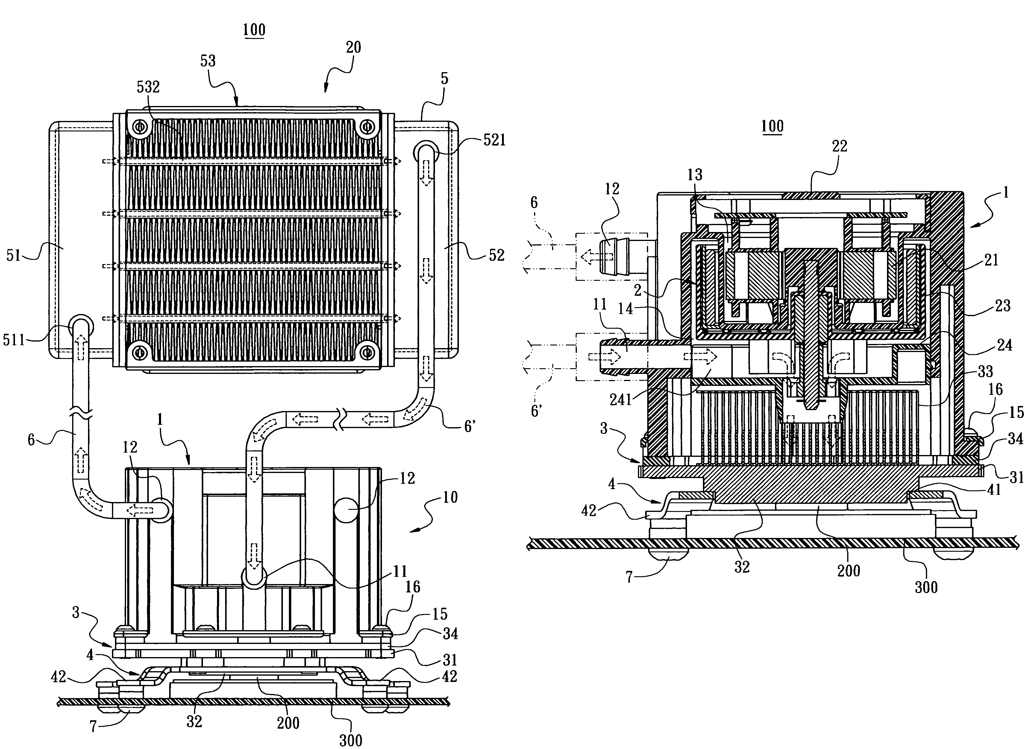
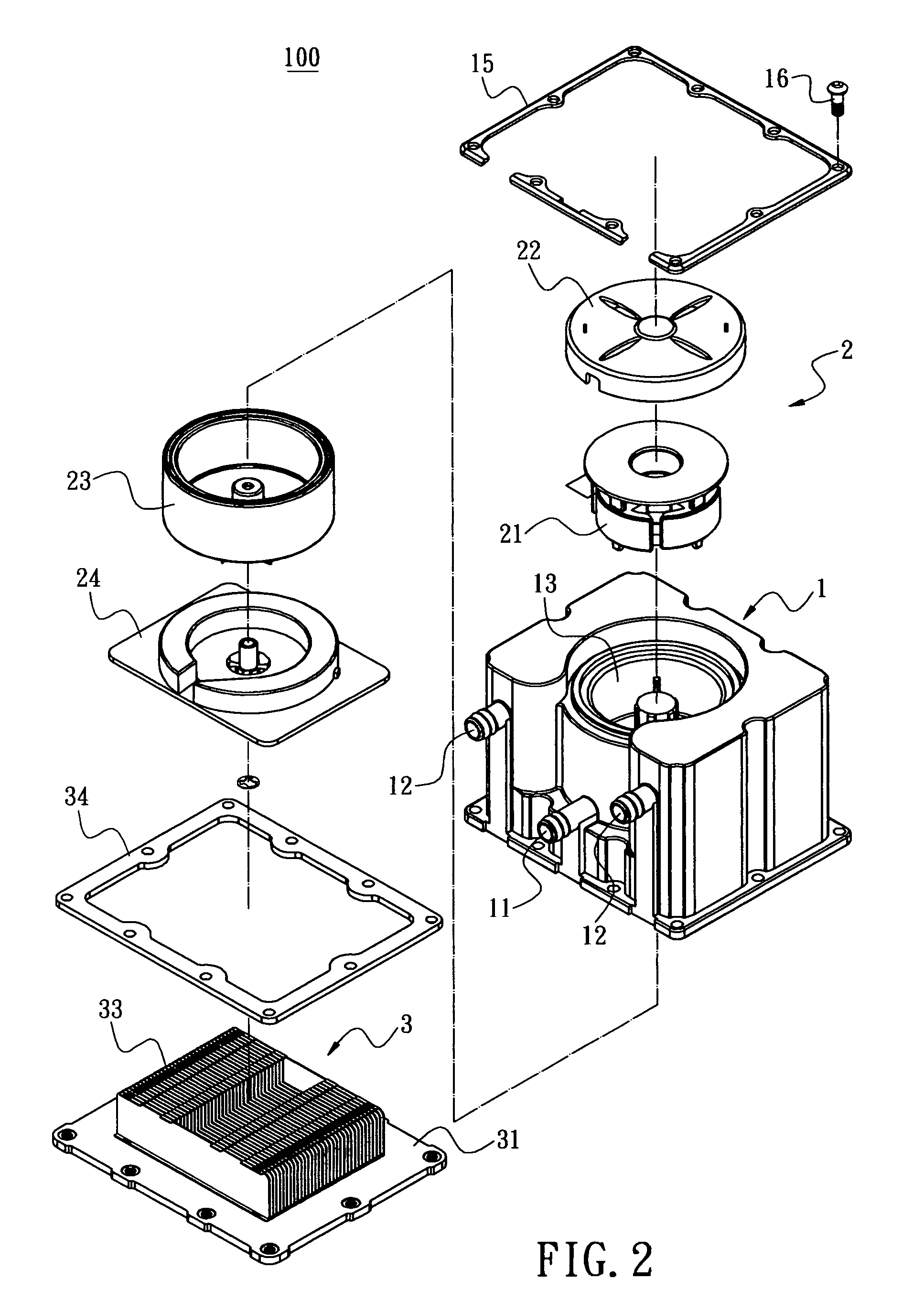
[0020]The present invention is intended to provide a liquid-cooling heat dissipation apparatus. FIGS. 2 and 3 show a preferred embodiment of the present invention, wherein the liquid-cooling heat dissipation apparatus 100 is used for heat dissipating a heat emitting device 200 (such as CPU 200). The heat dissipation apparatus 100 comprises a casing 1, a first compartment 13 defined in the casing 1 and used for mounting a liquid driving unit 2, a cooling plate module 3 arranged on bottom of the casing 1, a second compartment 14 defined between inner space of the casing 1 and filled with cooling liquid, at least one liquid inlet 11 and liquid outlet 12 defined on the casing 1 for communicating the second compartment 14. The cooling liquid is circulated when the liquid driving unit 2 operates.

[0021]In the present invention, the liquid driving unit 2 comprises a coil stage 21, an upper cover 22, an impeller stage 23, and a lower cover 24 in the first compartment 13. Moreover, at least o...


PUM


Abstract

A liquid-cooling heat dissipation apparatus includes a casing, a first compartment defined in the casing for assembling a liquid driving unit, a cooling plate module on bottom of the casing, a second compartment defined between an inner space of the casing and the cooling plate module and containing a cooling liquid therein. At least one liquid inlet and liquid outlet are defined on the casing and communicated through the second compartment. Therefore, the liquid driving unit and the cooling plate module can be advantageously integrated into the casing while the duct is reduced to achieve compact space. Moreover, the overall structure achieves liquid storing, circulating and heat conveying function.

Description

BACKGROUND OF THE INVENTION[0001]1. Field of the Invention[0002]The present invention relates to a liquid-cooling heat dissipation apparatus, and more particularly to a liquid-cooling heat dissipation apparatus used for heat emitting device such as a CPU.[0003]2. Description of Prior Art[0004]The computers are developed with more powerful function and computation speed. Beside performance issue, the product appearance, the construction and motherboard connection ways are also under extensive exploited. As downsize of form factor and increasing of processing speed, the heat dissipation for central processing unit (CPU) is also an important issue to solve.[0005]FIG. 1 shows a perspective view of a prior art liquid-cooling heat dissipation system 100a. As shown in this figure, the liquid-cooling heat dissipation system 100a comprises a heat dissipation stage 10a, a water outlet 101a and a water inlet 102a on both ends of the heat dissipation system stage 10a, respectively, a duct 103a ...

Claims


Application Information

Patent Timeline
Patent Type & Authority Patents(United States)
IPC IPC(8): H05K7/20
CPCH01L23/473H01L2924/0002H01L2924/00
Inventor DUAN, QIANG-FEILO, LIEH-FENG
Owner CHEMTRON RES
Why Eureka
Try Eureka