
Hole opener

a technology of hole opener and drill bit, which is applied in the direction of drilling rods, drilling pipes, cutting machines, etc., can solve the problems of vibration and whipping, lack of reliable centering in wells, and inability to provide quality installation of profile lines, so as to increase the serviceability and reliability of reamers.

Inactive Publication Date: 2008-02-05
OTKRYTOE AKTSIONERNOE OBSHSHESTVO TATNEFT IM V D SHASHINA
View PDF7 Cites 17 Cited by
  • Summary
  • Abstract
  • Description
  • Claims
  • Application Information

AI Technical Summary

Benefits of technology

"The invention is a well reamer that improves its serviceability and reliability. It includes a housing with inclined slots and a central straight-through channel, in which a rod is placed and spring-loaded towards a lower end of the housing. The housing has legs with journals, and rolling cutters are provided and supported by the journals. The pushers are made in the form of cylindrical pistons, which are tightened relative to the straight-through channel and annulus environment. The central straight-through channel of the housing communicates with the environment through first and second holes in the walls of the housing and the rod. This design allows for better performance and durability of the reamer."

Problems solved by technology

A shortcoming of the known device is the lack of reliable centering in a well, since no more than two operating elements may be provided in the housing without detriment to its strength.
This results in vibration and whipping during the process of well reaming.
In so doing the surface of the reamed well section becomes irregular, which does not provide for quality installation of profile liner during well drilling.
Additionally, in the known reamer, the rolling cutters are fixed on cantilevered legs without fixing the free ends of journals, which lowers the strength of operating elements and leads to breakage at heavy mechanical loads.
Shortcomings of this device include low serviceability and reliability due to presence in its design of a ring piston, rigidly connected with the rod, and pushers of supports in the form of two-member links, which cannot withstand heavy power loads.
Additionally, the design of the known reamer does not allow control over settings of the operating elements into working position.

Method used


Image

  • Hole opener
  • Hole opener
  • Hole opener

Examples


Embodiment Construction

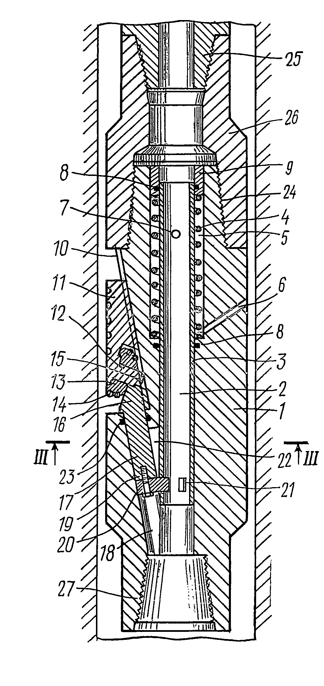
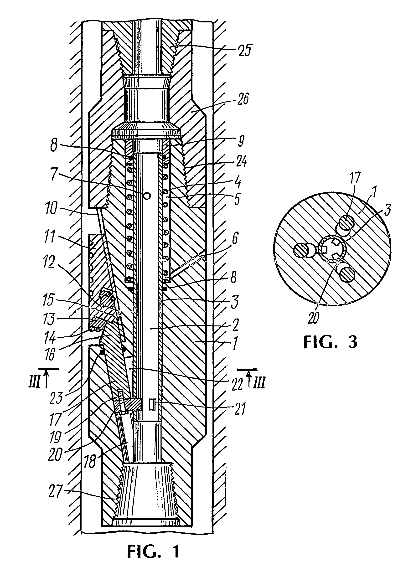
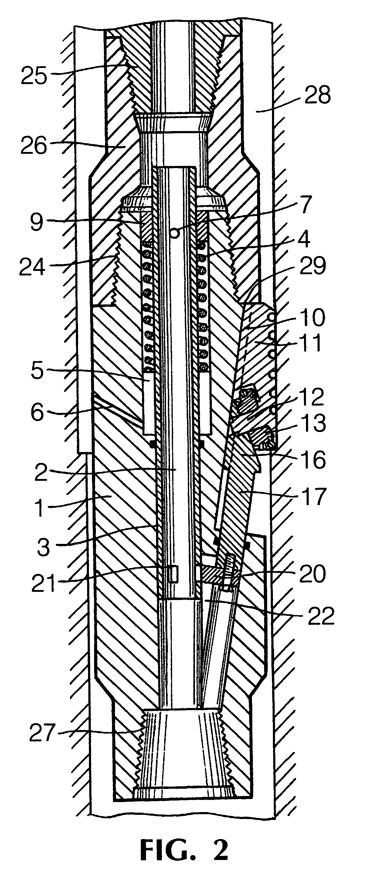
[0012]A well reamer (FIG. 1) comprises a housing 1 with a central straight-through channel 2, in which rod 3 is placed and spring-loaded by a spring 4 towards the lower end of the housing 1. The spring 4 is positioned in a chamber 5, which is formed by an inner wall of the housing 1 and an outer wall of the rod 3. The chamber 5 communicates through first holes 6 in the wall of the housing 1 with the environment and through second holes 7 in the wall of the rod 3—with the central straight-through channel 2 of the housing 1. The chamber 5 is isolated from the straight-through channel 2 by seals 8, and the second holes 7 of the rod 3 may be covered by a thrust bushing 9 after the rod 3 has come to the upper most position.

[0013]The housing 1 has outer inclined first slots 10 (FIG. 1, 3) of “dovetail” type, in which legs 11 are provided with journals 12. On the journals 12, cutters 13 with hard-alloy teeth 14 are provided for rotation about the journals 12. The legs 11, acting as calibra...


PUM


Abstract

The invention relates to well reamer for borehole reaming within a specified interval. The well reamer has a housing with inclined slots, radial holes and a central straight-through channel, in which a spring-loaded rod with holes in the upper and lower parts is located. The upper holes of the rod are covered when the operating elements are extended into an operating position. A plurality of legs, including cutters rotatably supported on the legs, are moved by pistons between an operating position and a transport position along the inclined slots. Free-ends of the pistons may be connected to the rod by sliders, which are movable radially into openings in the rod to connect the rod to the pistons to move the rod with the legs.

Description

FIELD OF INVENTION[0001]The invention relates to drilling technique, in particular, to devices for borehole reaming within a specified interval.DESCRIPTION OF RELATED ART[0002]There is known a well reamer, comprising a housing with inclined slots and a piston placed in it which is spring-loaded through a rod, legs with journals fixed in inclined slots of the housing, on which journals cantilevered rolling cutters are provided (Inventor's certificate of the USSR No 582373, class E21B 7 / 28, 1971).[0003]A shortcoming of the known device is the lack of reliable centering in a well, since no more than two operating elements may be provided in the housing without detriment to its strength. This results in vibration and whipping during the process of well reaming. In so doing the surface of the reamed well section becomes irregular, which does not provide for quality installation of profile liner during well drilling. The rate of borehole reaming is also low.[0004]Additionally, in the know...

Claims


Application Information

Patent Timeline
Patent Type & Authority Patents(United States)
IPC IPC(8): E21B10/32E21B10/34E21B7/28
CPCE21B10/322
Inventor TAKHAUNDINOV, SHAFAGAT FAKHRAZOVICHIBRAGIMOV, NAIL GABDULBARIEVICHKAVEEV, KHAMIT ZAGIROVICHABDRAKHMANOV, GABDRASHIT SULTANOVICHKHAMITIANOV, NIGAMATIAN KHAMITOVICHKASHAPOV, ILGIZ KAMAEVICHABDRAKHMANOV, RUSLAN GABDRASHITOVICH
Owner OTKRYTOE AKTSIONERNOE OBSHSHESTVO TATNEFT IM V D SHASHINA
Learn More