Static mixer

a mixer and mixer technology, applied in the direction of mixers, mixing, chemistry apparatus and processes, etc., can solve the problems of eventual plugging of mixers, and achieve the effects of reducing pressure drop, high mixing efficiency, and reducing dead volumes

Inactive Publication Date: 2008-02-05
MEDMIX SWITZERLAND AG
View PDF18 Cites 29 Cited by
  • Summary
  • Abstract
  • Description
  • Claims
  • Application Information

AI Technical Summary

Benefits of technology

[0005]On the background of this prior art, it is the object of the present invention to provide a static mixer achieving a high mixing efficiency with reduced dead volumes and reduced pressure drop. This object is attained by a static mixer wherein said mixing element comprises a transversal edge and a following transversal guide wall and at least two guide walls ending into a separating edge each with lateral end sections and with at least one bottom section disposed between said guide walls, thereby defining at least one opening on one side of said transversal edge and at least two openings on the other side of said transversal edge.

Problems solved by technology

Although mixers of this kind achieve a better mixing of the components with reference to its length and exhibit a smaller pressure drop than conventional mixers using mixing helixes, they include relatively large dead volumes in which the composition will harden, thereby leading to an eventual plugging of the mixer.

Method used


Image

  • Static mixer
  • Static mixer
  • Static mixer

Examples


Embodiment Construction

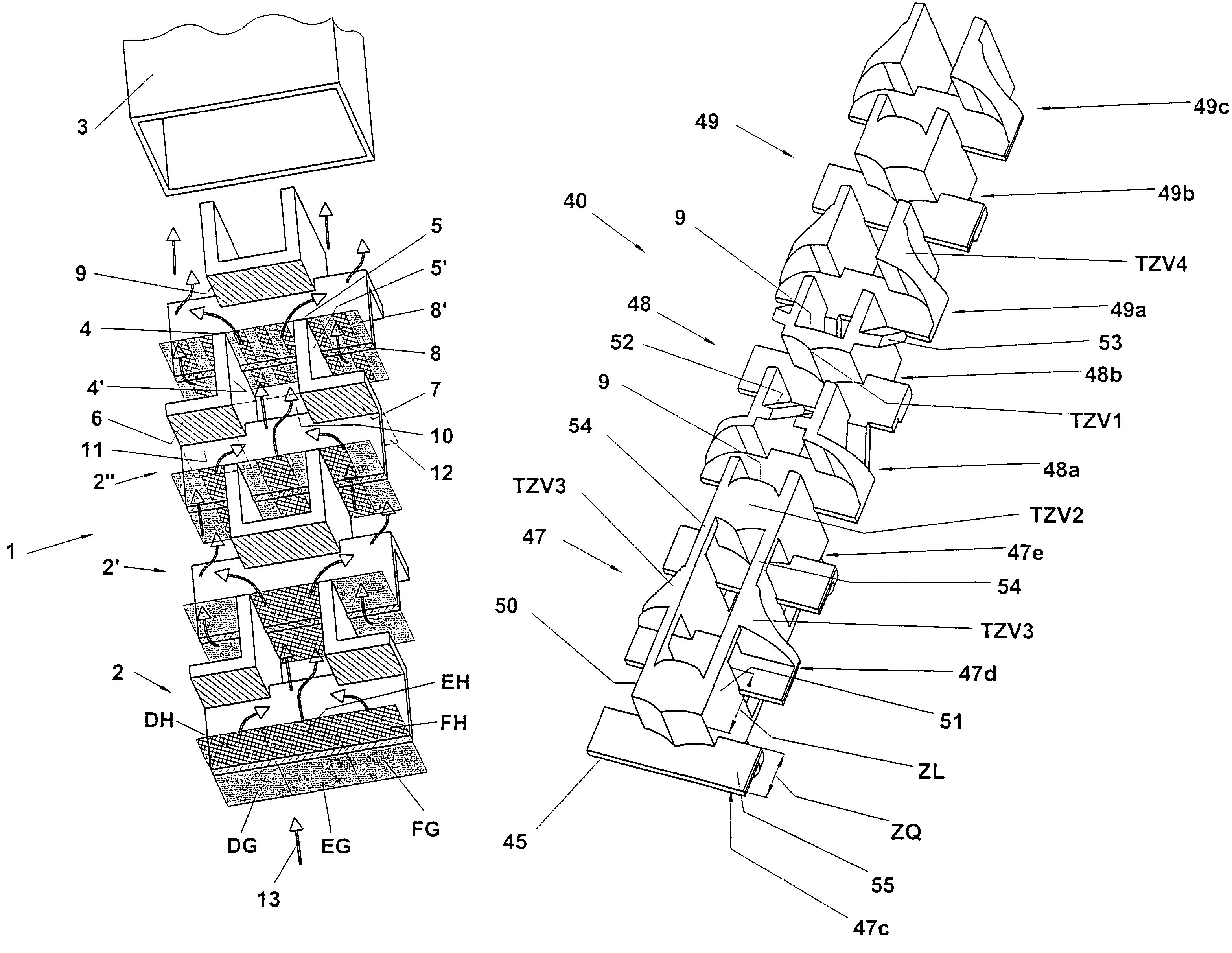
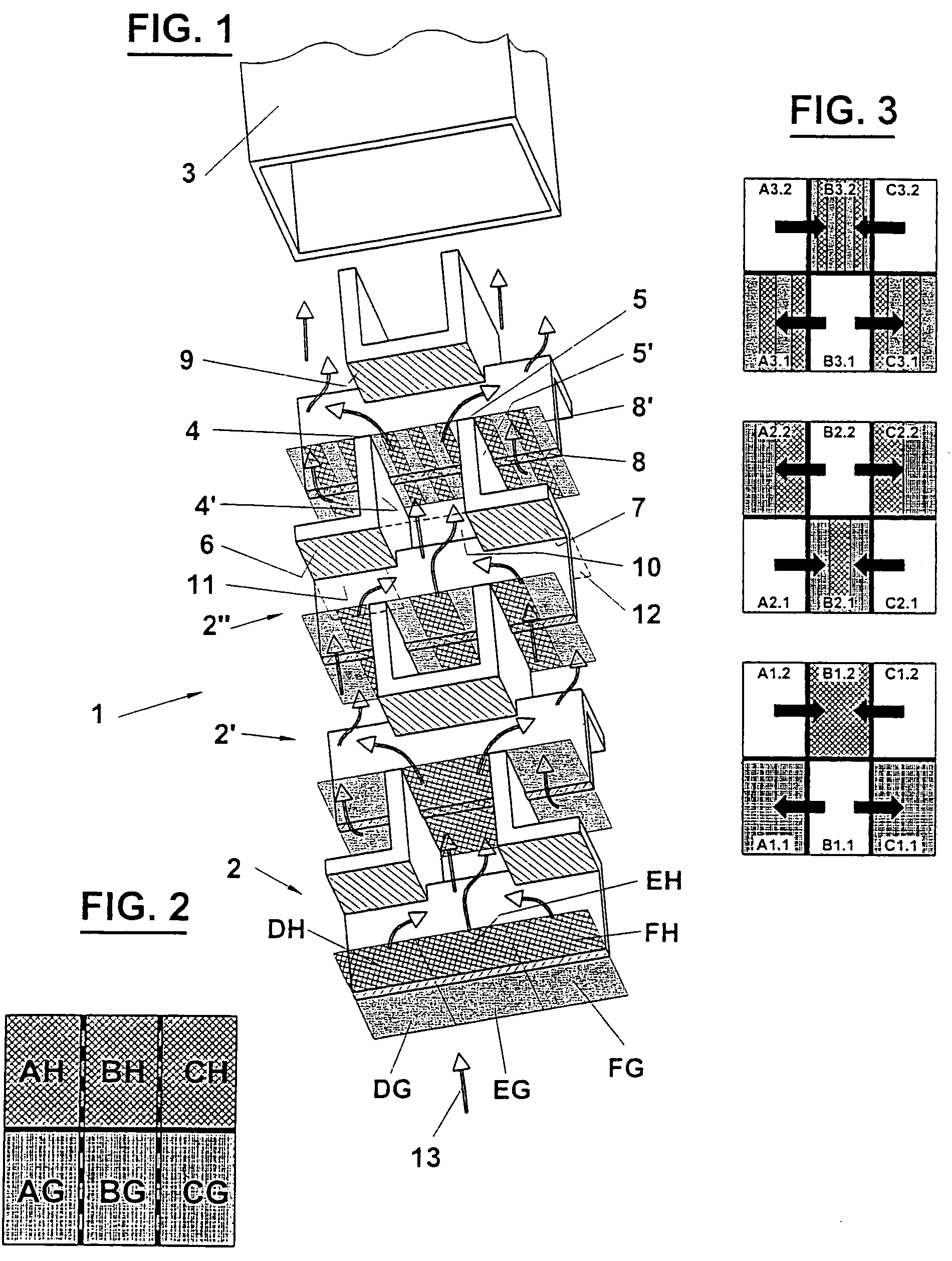
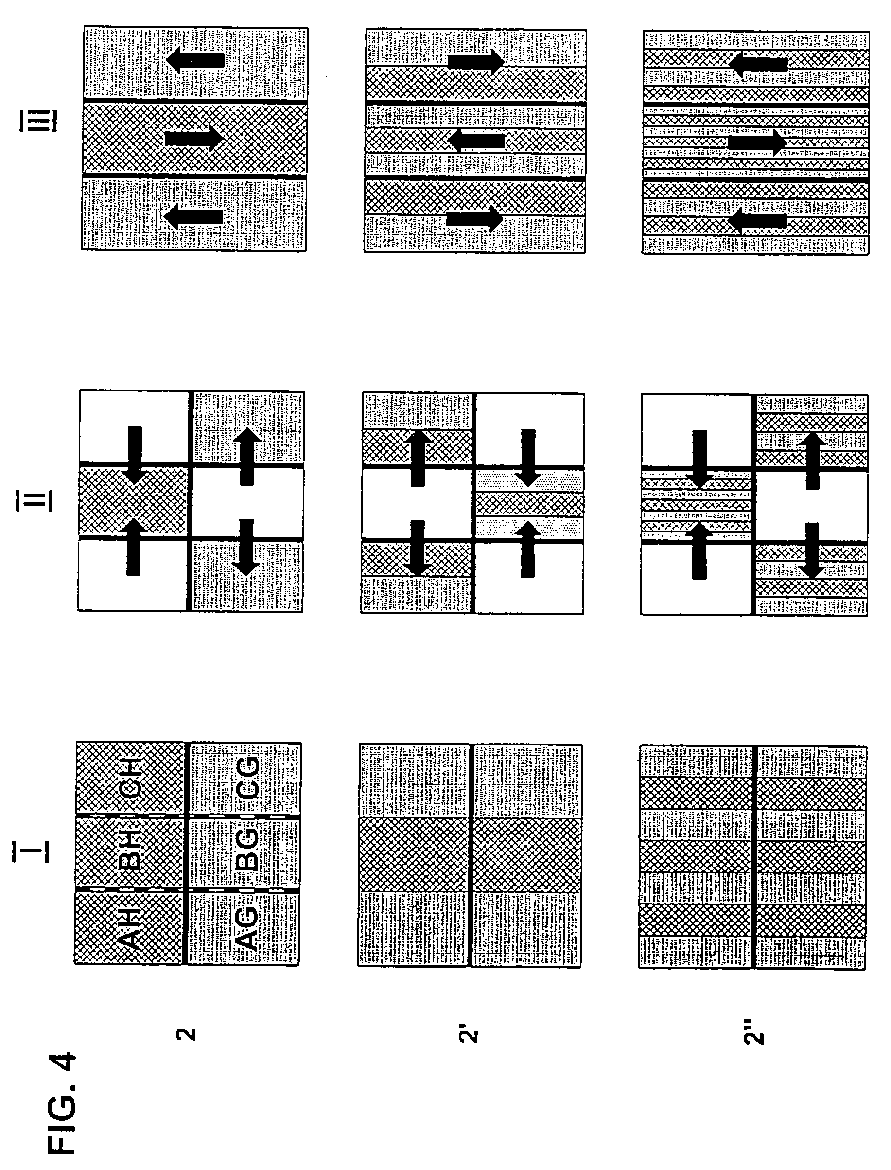
[0024]FIG. 1 illustrates a detail of a first exemplary embodiment of a mixer 1 of the invention that comprises a number of identical mixing elements 2, 2′, and 2″, which are superimposed on one another while each successive element is rotated by 180° with respect to the longitudinal axis. Mixing enclosure 3 is schematically shown at one end.

[0025]Seen in the flow direction, i.e. from the bottom of the drawing, one end of each individual mixing element 2 comprises a transversal edge 8 of a transversal guide wall 8′ that is followed by two end sections 6 and 7 extending perpendicularly thereto and including complementary lateral openings 11 and 12, and by a bottom section 9 and a complementary bottom section opening 10, the latter extending between two guide walls 4′, 5′ each of which ends in a respective separating edge 4, 5, where the guide walls are aligned in parallel with the longitudinal center axis. In the present example, the end sections extend over half the length of the sep...


PUM


Abstract

The static mixer comprising mixing elements for separating the material to be mixed into a plurality of streams and a mechanism for the layered junction of the same, a transversal edge and guide walls that extend at an angle to said transversal edge, as well as deflecting elements arranged at an angle to the longitudinal axis and provided with openings, includes mixing elements comprising a transversal edge and a following transversal guide wall and at least two guide walls with lateral end sections and at least one bottom section disposed between said guide walls, thereby defining at least one opening on one side of said transversal edge and at least two openings on the other side of said transversal edge. In addition to a high mixing efficiency and a low pressure drop, a mixer of this kind provides reduced dead volumes and is thus more effective than mixers of the prior art.

Description

[0001]This application is a continuation application of U.S. patent application Ser. No. 10 / 727,049, filed Dec. 4, 2003, which is abandoned.BACKGROUND OF THE INVENTION[0002]The present invention relates to a static mixer comprising mixing elements for separating the components to be mixed into a plurality of streams, as well as means for the layered junction of the same, including a transversal edge and guide walls that extend at an angle to said transversal edge, as well as deflecting elements arranged at an angle to the longitudinal axis and provided with openings.PRIOR ART[0003]A static mixer of this kind is e.g. known from U.S. Pat. No. 5,851,067. This patent in turn is a further development of U.S. Pat. No. 5,944,419. These references disclose a mixer that is divided into chambered strings; according to the first cited U.S. patent, four chambered strings are created by four alternately disposed passages and the mixer further comprises re-layering chambers. In the second cited m...

Claims


Application Information

Patent Timeline
Patent Type & Authority Patents(United States)
IPC IPC(8): B01F5/06B01F5/00
CPCB01F5/0617B01F5/064B01F2215/0039B01F2215/0427B01F25/43151B01F25/4321B01F25/432B01F2101/2305B01F25/00B01F25/40
Inventor KELLER, WILHELM A.
Owner MEDMIX SWITZERLAND AG
Why Eureka
Try Eureka