Charger assembly for a power cell for an electrical tool

a technology of power cell and charger, which is applied in the direction of electric vehicles, electric generators, transportation and packaging, etc., can solve the problems of charger base (60/b>) to malfunction, users may be shocked,

Inactive Publication Date: 2008-02-05
TECHWAY INDAL
View PDF3 Cites 27 Cited by
  • Summary
  • Abstract
  • Description
  • Claims
  • Application Information

AI Technical Summary

Benefits of technology

[0009]The main objective of the present invention is to provide a power cell and charger assembly that can be engaged firmly to ensure electrical continuity and protect electrodes from corroding and becoming dusty.
[0013]By setting the locking devices, the power cell is firmly attached to and conveniently detached from the charger base. Additionally, the sliding cover protects the electrodes from rusting or becoming dusty when the charger base is not in use.

Problems solved by technology

However, the conventional charger assembly for a power cell has some drawbacks caused from its structure.
Moreover, the electrodes (644) on the charger base (60) are exposed to the environment, which causes two problems.
First, users may be shocked when they inadvertently touch the exposed electrodes on the charger base (60).
Second, contacts on the charger base (60) easily corrode or become dusty after a period of time without any cover, which may cause the charger base (60) to malfunction.

Method used


Image

  • Charger assembly for a power cell for an electrical tool
  • Charger assembly for a power cell for an electrical tool
  • Charger assembly for a power cell for an electrical tool

Examples


Embodiment Construction

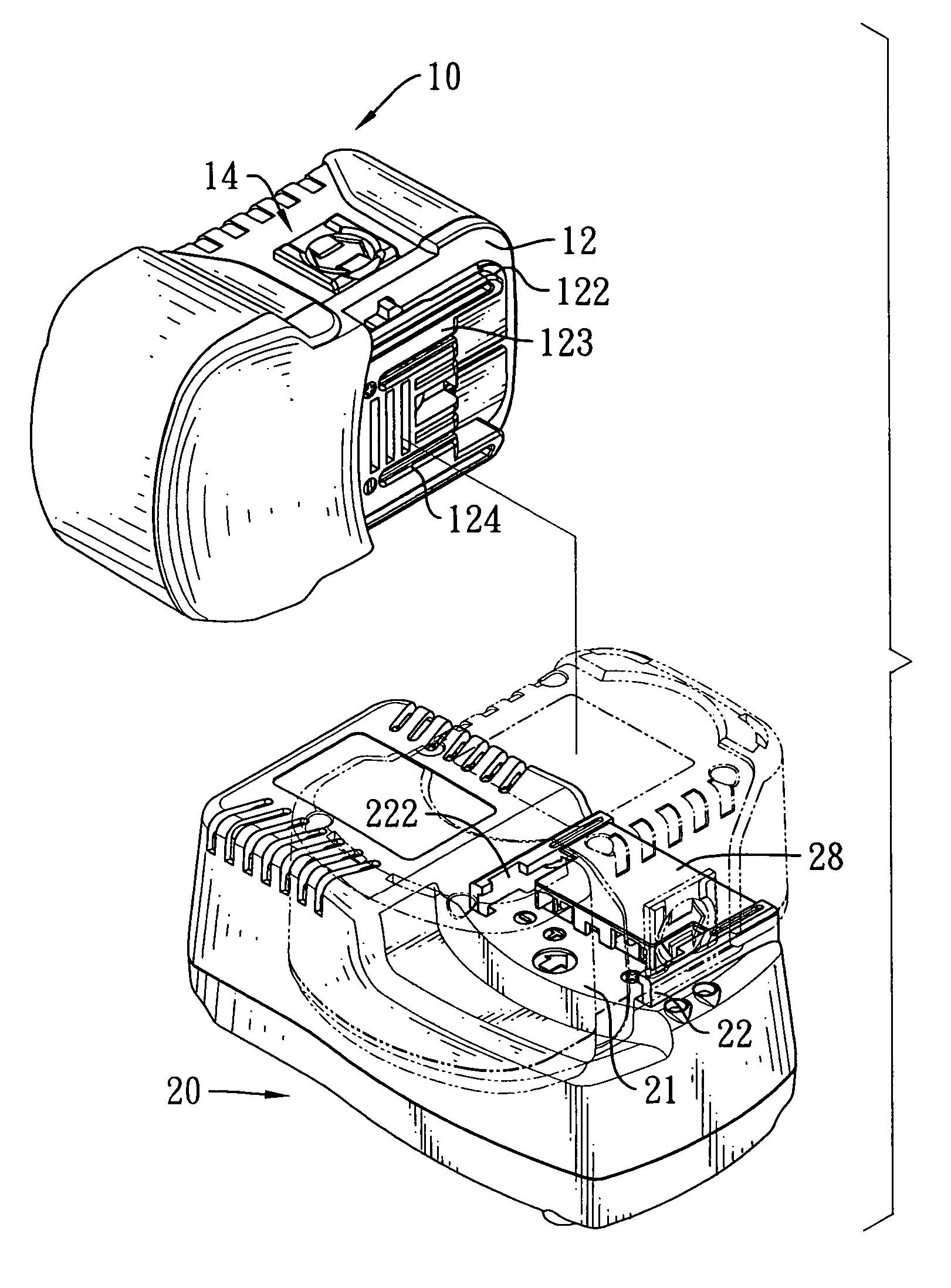
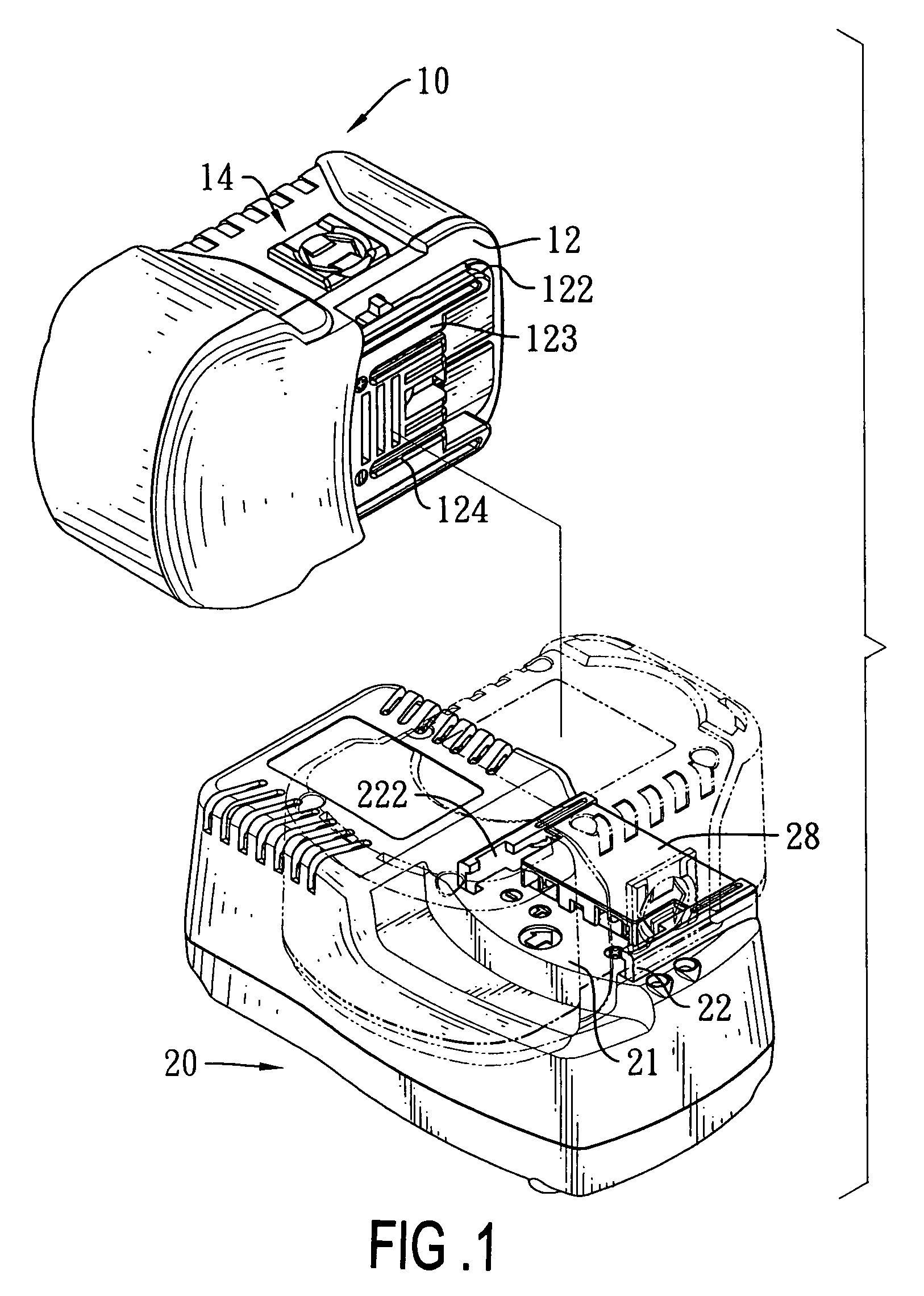
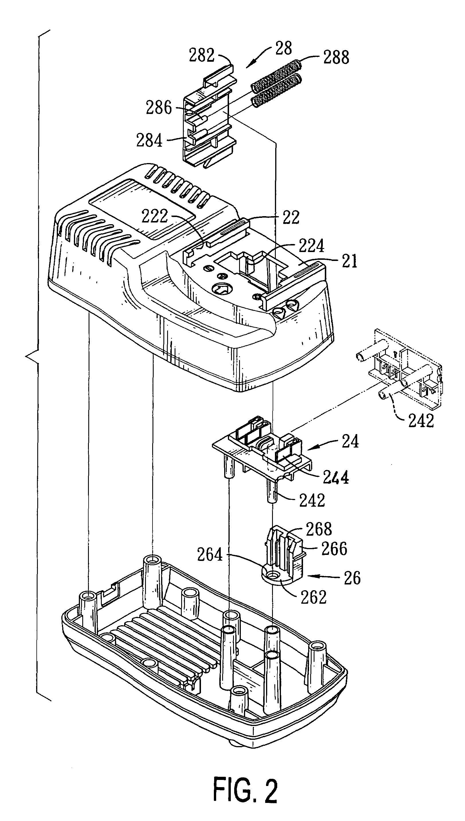
[0023]A charger assembly for a power cell for an electrical tool in accordance with the present invention comprises a power cell and a charger base. The power cell has two locking devices, and the charger base has a sliding cover selectively covering multiple electrodes. The locking devices allow the power cell to be firmly attached to and conveniently detached from the charger base. Additionally, the sliding cover protects the electrodes from rusting or becoming dusty when the power cell is not mounted on the charger base.

[0024]With reference to FIGS. 1 to 3, a preferred embodiment of the charger assembly for a power cell in accordance with the present invention comprises a power cell (10) and a charger base (20).

[0025]The power cell (10) has a box-like casing, two flanges (122), two through holes (126), a contact surface (123), multiple elongated electrodes (124) and two locking devices (14). The casing has a bottom contact face (12) and two sides. Each side has a mounting hole an...


PUM

PropertyMeasurementUnit
electrical continuityaaaaaaaaaa
electricalaaaaaaaaaa
electrical connectionaaaaaaaaaa

Abstract

A power cell and charger assembly for an electrical tool has a power cell with two locking devices and a charger base with a sliding cover. The power cell and the charger base slidably engage each other. By setting the locking devices composed of push buttons and biasing members, the power cell and the charger base can be firmly engaged and conveniently detached. Additionally, the sliding cover protects the electrodes from corroding or becoming dusty when power cell is not attached to the charger base. Therefore, the power cell is conveniently attached to or disengaged from the charger base, and the power cell and charger assembly has long life span when the electrodes are kept clean by the sliding cover.

Description

BACKGROUND OF THE INVENTION[0001]1. Field of the Invention[0002]The invention relates to a charger assembly for a power cell for an electrical tool, and more particularly to a charger assembly for a power cell that can be detached conveniently and is dustproof.[0003]2. Description of Related Art[0004]With reference to FIG. 8, a conventional charger assembly for a power cell of an electrical tool mainly comprises a power cell (50) and a charger base (60).[0005]The power cell (50) is substantially a parallelepiped and has a bottom (not numbered), a contact face and a recessed track (54). The recessed track (54) is defined in the contact face (52) and has two sidewalls, two grooves (542), a contact surface (not numbered) and multiple electrodes (544). The grooves (542) are defined respectively in the two sidewalls, and the contact surface is defined between the sidewalls. The electrodes (544) protrude from the contact surface of the recessed track (54).[0006]The charger base (60) is su...

Claims


Application Information

Patent Timeline
Patent Type & Authority Patents(United States)
IPC IPC(8): H01M10/46
CPCH02J7/0045H01M10/46Y02E60/10
Inventor LIN, CHUN-HSIAO
Owner TECHWAY INDAL
Why Eureka
Try Eureka