Cooling failure mitigation for an electronics enclosure

a technology for cooling enclosures and electronics, applied in the direction of cooling/ventilation/heating modifications, electrical apparatus casings/cabinets/drawers, instruments, etc., can solve problems such as system shutdown, component failure and/or system shutdown, instantaneous temperature rise within the enclosure, etc., to achieve an orderly shutdown and reduce the risk of system shutdown or failur

Active Publication Date: 2008-02-05
ORACLE INT CORP
View PDF61 Cites 22 Cited by
  • Summary
  • Abstract
  • Description
  • Claims
  • Application Information

AI Technical Summary

Benefits of technology

[0007]In accordance with another aspect of the invention, a method for cooling one or more electronic components positioned in an enclosure includes providing an air cooling element within the enclosure. An airflow is generated across the air cooling element and the one or more electronic components. Upon a failure in the cooling element, a phase change material positioned within the enclosure cools the airflow.

Problems solved by technology

Due to their high power consumption, these electronic components generate heat, which if let unabated, can quickly lead to component failure and / or system shutdown.
Because of the very high power dissipation in the enclosure, any failure in the cooling system causes an instantaneous temperature rise within the enclosure.
As a result, a system shutdown or failure may occur without sufficient time for an orderly shutdown.
Consequently, critical data that is not stored in memory is often lost.

Method used


Image

  • Cooling failure mitigation for an electronics enclosure
  • Cooling failure mitigation for an electronics enclosure
  • Cooling failure mitigation for an electronics enclosure

Examples


Embodiment Construction

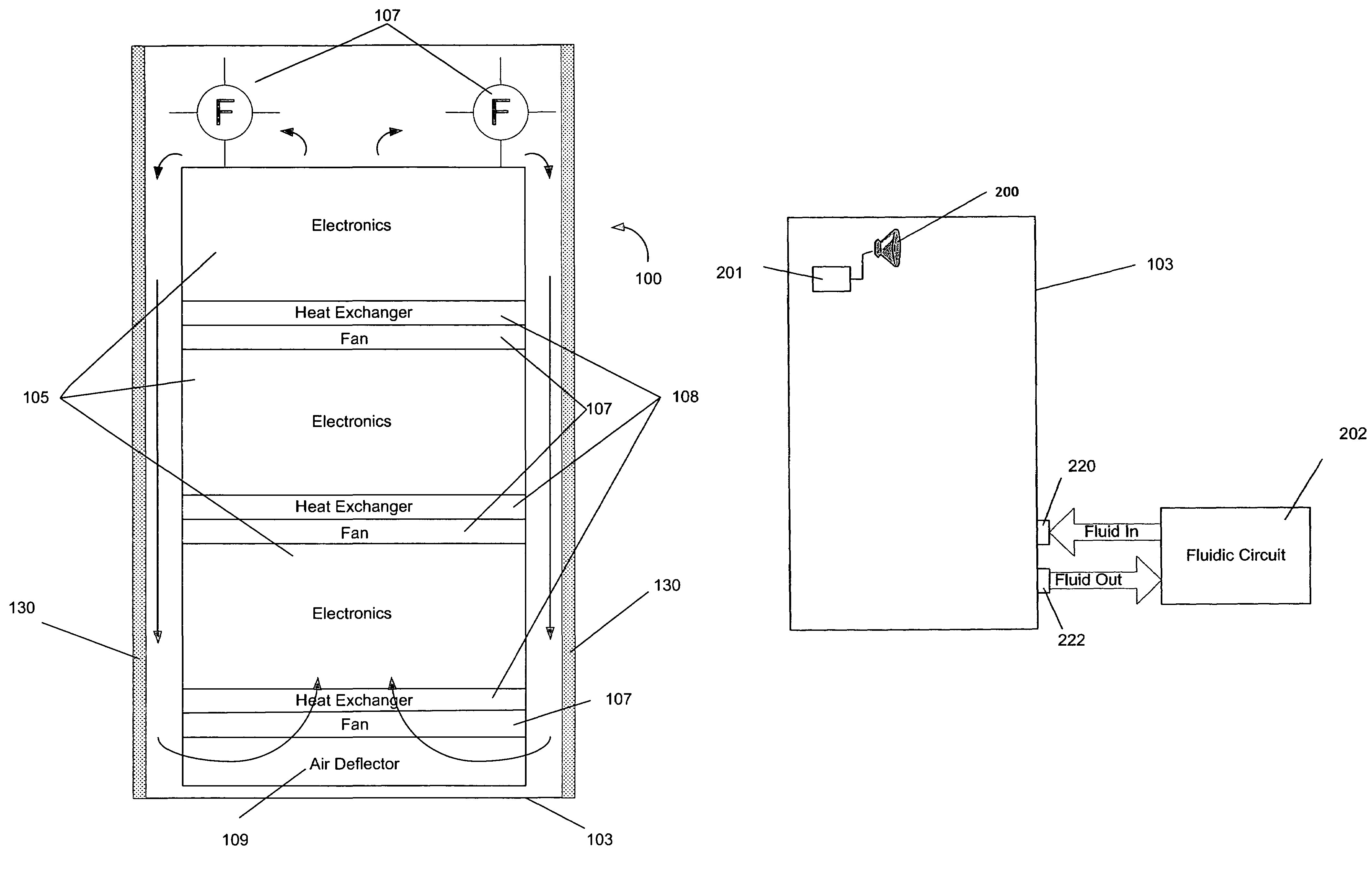
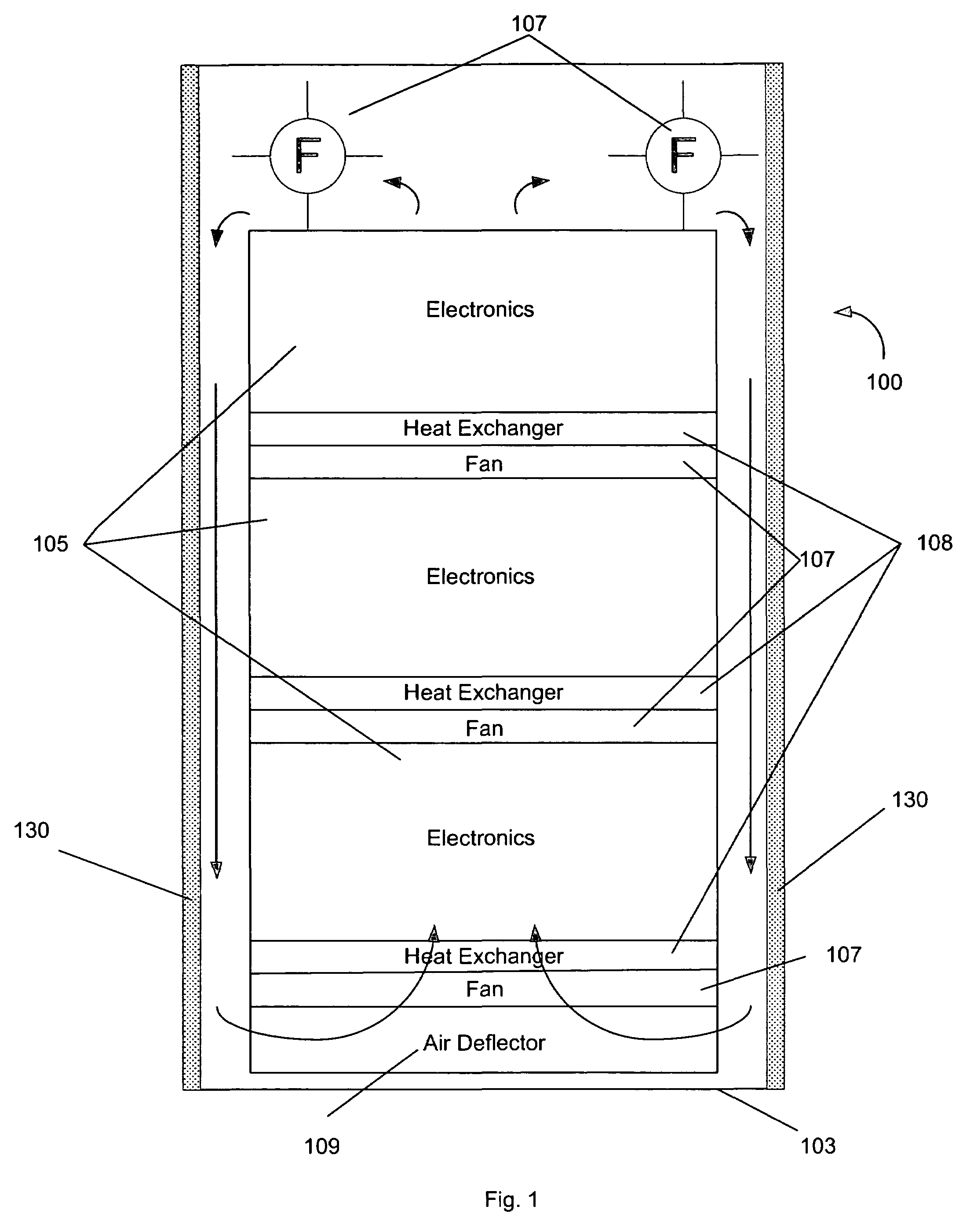
[0015]In illustrative embodiments of the invention, a system and method is presented that allows for orderly shutdown of electronic components in an enclosure in the event of a cooling failure. To those ends, the system includes a phase change material which, upon a failure in a cooling element, maintains a predetermined temperature until an orderly shutdown can be performed. Details of various embodiments are discussed below.

[0016]FIG. 1 is a diagram illustrating a front view of a cooling system 100 that permits orderly shutdown of electronic components 105 in the event of a cooling failure, in accordance with one embodiment of the invention. The cooling system 100 is based on a substantially closed, recirculating airflow within an enclosure 103. Heat dissipated by the electronic components 105 is transferred to the airflow. At least one heat exchanger 108 serves to remove heat from the air.

[0017]The enclosure 103 may be of varying size and shape and include one or more doors for e...


PUM


Abstract

A system for permitting orderly shutdown of electronic components. The system includes an enclosure populated with one or more electronic components. A fan positioned within the enclosure generates an airflow across the one or more electronic components, the airflow being cooled by a heat exchanger. A phase change material is positioned within the enclosure to absorb heat from the airflow in the event of a failure associated with the heat exchanger.

Description

TECHNICAL FIELD[0001]The present invention generally relates to a system and method for mitigating failure of a cooling system for electronic components contained in an enclosure.BACKGROUND ART[0002]Various high power electronic components are often housed within an enclosure.[0003]Due to their high power consumption, these electronic components generate heat, which if let unabated, can quickly lead to component failure and / or system shutdown.[0004]To cool the electronic components, a cooling system is integrated within the enclosure. A typical cooling system includes a fan which generates a recirculating airflow over the electronic components. The airflow absorbs heat from, and cools, the electronic components. A fluidic circuit recirculates fluid through a heat exchanger positioned within the airflow, cooling the heated air. The heated fluid exiting the heat exchanger can be directed to, and cooled at, a location external to the enclosure.[0005]Because of the very high power dissi...

Claims


Application Information

Patent Timeline
Patent Type & Authority Patents(United States)
IPC IPC(8): H05K7/20F28D21/00G06F1/20
CPCG06F1/20G06F1/206H05K7/20754
Inventor NOVOTNY, SHLOMO
Owner ORACLE INT CORP
Why Eureka
Try Eureka