Rigging system for loudspeaker arrays

Active Publication Date: 2008-02-12
ADAMSON ALAN BROCK
View PDF12 Cites 68 Cited by
  • Summary
  • Abstract
  • Description
  • Claims
  • Application Information

AI Technical Summary

Benefits of technology

[0016]It is the primary object of the present invention to provide a rigging system for loudspeaker cabinets or enclosures which is designed to be mounted within the speaker cabinets in such a way that no secondary suspension components are required for connecting adjacent speakers to one another in a vertical array and such that all connecting elements are carried by each speaker in an array so that the components are not misplaced during transport, assembly or disassembly of the array.
[0017]It is yet another object of the present invention to provide a rigging system for loudspeaker speaker cabinets which allows predetermined angular adjustment to be made between adjacent cabinets very easily and quickly by simply rotating rigging disks to a predetermined position and thereafter locking the disks with locking elements associated with each of the cabinets.
[0018]It is also an object of the present invention to provide a method for assembling a plurality of loudspeaker cabinets in

Problems solved by technology

Such an arrangement is extremely bulky and complex and requires several people to manipulate to accurately position the speakers relative to one another.
Further, there is no predetermined adjustment possible and, therefore, the exact positioning of the speakers relative to one another is not possible without measuring the spacing between each speaker relative to the suspension cables or chains.
Such a system is not conducive to quick assembly o

Method used


Image

  • Rigging system for loudspeaker arrays
  • Rigging system for loudspeaker arrays
  • Rigging system for loudspeaker arrays

Examples


Example

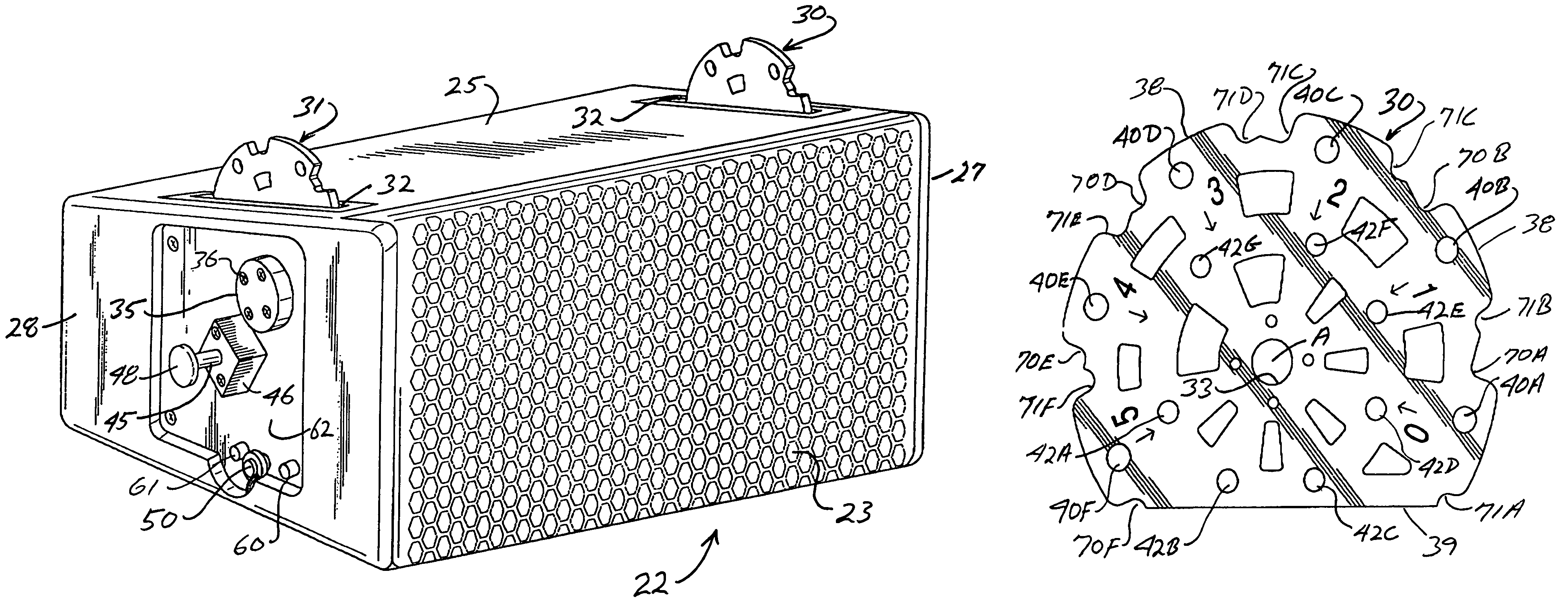
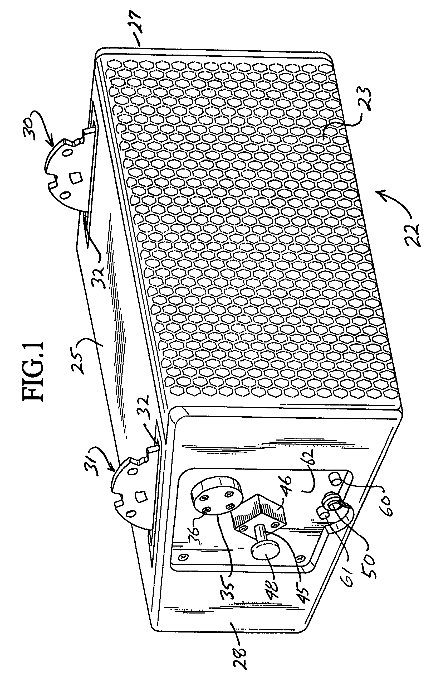
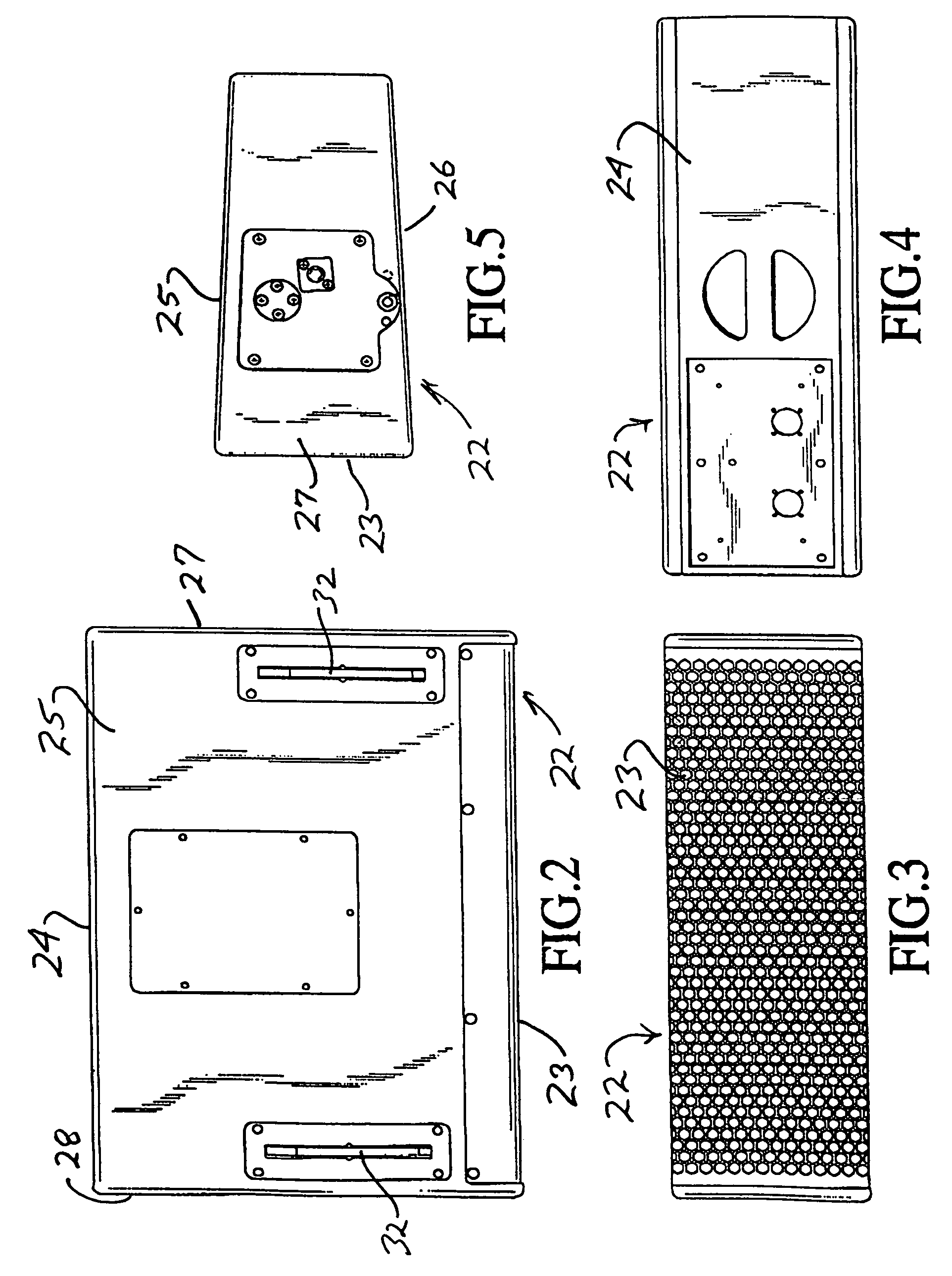
[0035]With continued reference to the drawing figures, the rigging system of the present invention is designed specifically for mounting a plurality of loudspeaker cabinets into a vertical array, such as shown at 20FIG. 10, wherein the orientation between each loudspeaker cabinet may be set at a predetermined angle or the cabinets may be aligned such that the outputs therefrom form a planar acoustical wavefront as opposed to a slightly curved wavefront as illustrated in the drawing figure.

[0036]The present invention incorporates a rigging system which is specifically designed to be retained within each of the loudspeaker cabinets. In this respect, the rigging system does not rely on exterior components to secure the loudspeaker cabinets to one another in a predetermined angular array and, thus, offers a benefit over prior art rigging systems.

[0037]Each of the loudspeaker cabinet 22 houses acoustical transducers for generating various sounds at varying frequencies. By way of example,...


PUM


Abstract

A rigging system for angularly adjusting the output portions of a plurality of loudspeaker cabinets wherein each of the cabinets includes a pair of rotatably adjustable rigging disks which protrude outwardly thereof which are selectively receivable within an adjacent cabinet. Each cabinet has a first locking element for securing the disks therein with respect thereto and second locking element or elements for selectively securing protruding portions of disks of an adjacent cabinet whereby an angle of the output portions of each cabinet may be adjusted from substantially a planar orientation to a curved orientation to thereby change the overall wavefront characteristics of sound issuing from a vertical array of attached loudspeaker cabinets.

Description

BACKGROUND OF THE INVENTION[0001]1. Field of the Invention[0002]This invention is generally directed to rigging systems used to secure a plurality of loudspeakers in a vertical array and more specifically to a rigging system which incorporates speaker mounted disks which may be selectively adjustably rotated and secured in a position to thereby change an angular orientation or tilt angle of loudspeaker cabinets relative to one another without suspension cables and the like. The rigging system is designed in such a manner that a single person may easily configure a plurality of loudspeakers into a predetermined angular relationship in a vertical array depending upon the acoustical characteristics to be obtained within a specific environment.[0003]2. Brief Description of the Related Art[0004]Speakers which are used in environments such as theaters, churches, concert halls and the like are generally arranged relative to one another depending upon the acoustical characteristics of the e...

Claims


Application Information

Patent Timeline
IPC IPC(8): H05K13/04A47B46/00A47B57/04
CPCH04R1/026
Inventor ADAMSON, ALAN BROCK
Owner ADAMSON ALAN BROCK
Why Eureka
Try Eureka