Side impact load transmitting structure

a transmission structure and side impact technology, applied in the direction of roofs, movable seats, pedestrian/occupant safety arrangements, etc., can solve the problem of no solution suggested in regard to

Inactive Publication Date: 2008-02-12
TOYOTA JIDOSHA KK
View PDF27 Cites 21 Cited by
  • Summary
  • Abstract
  • Description
  • Claims
  • Application Information

AI Technical Summary

Benefits of technology

[0007]In view of this circumstance, the present invention provides a side impact load transmitting structure that is configured to suppress the downward movement of the load transmitting member at the time of a side impact collision to allow more of the side impact load to be transmitted to the tunnel portion through the load transmitting member and which can reliably ensure a load transmission path.

Problems solved by technology

However, this conventional structure is configured to suppress the outer side (collision side) of the seat in the vehicle width direction from rising up at the time of a side impact collision, and no solutions are suggested in regard to when the collision side of the load transmitting member moves downward.

Method used


Image

  • Side impact load transmitting structure
  • Side impact load transmitting structure
  • Side impact load transmitting structure

Examples


first embodiment

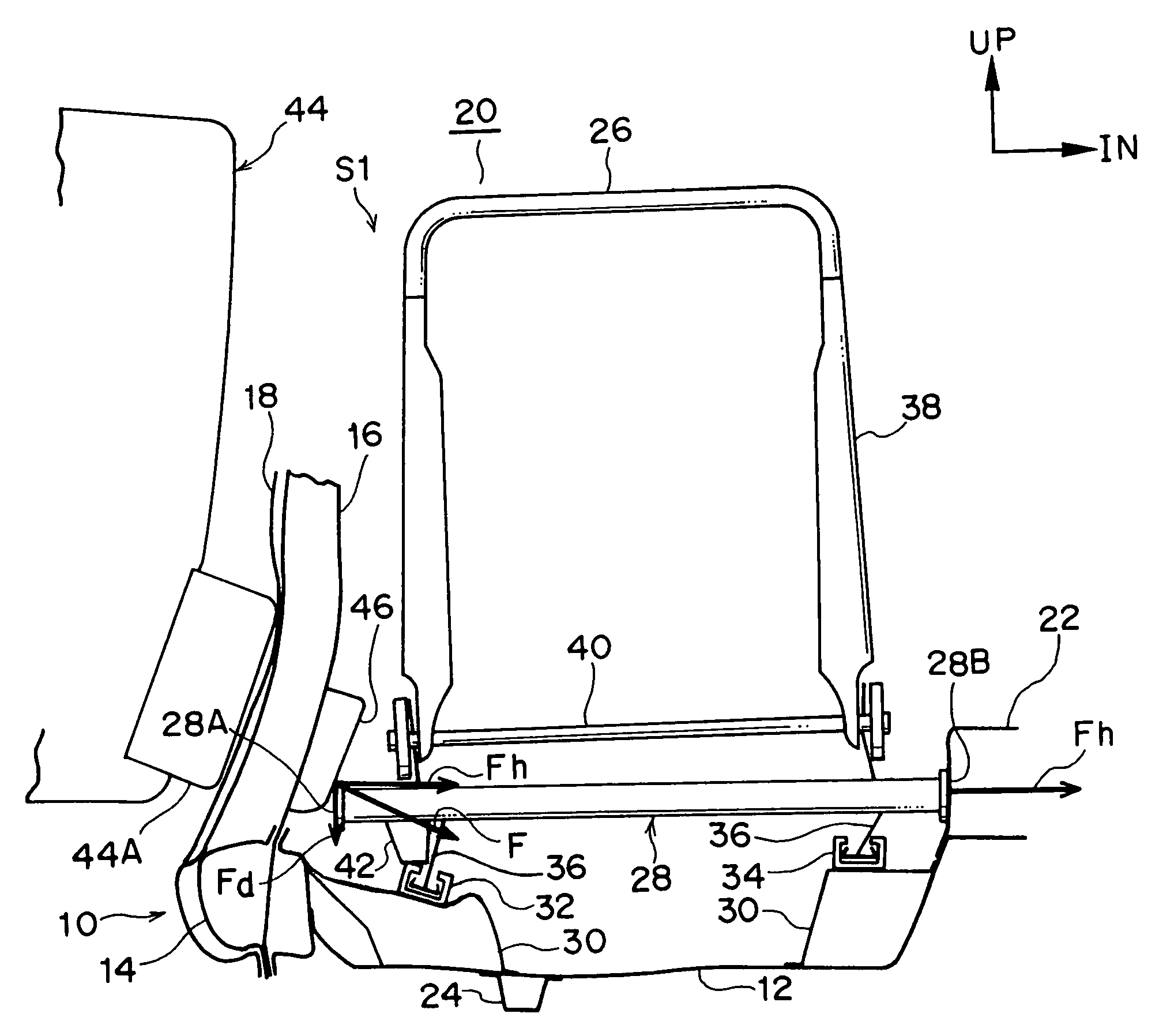
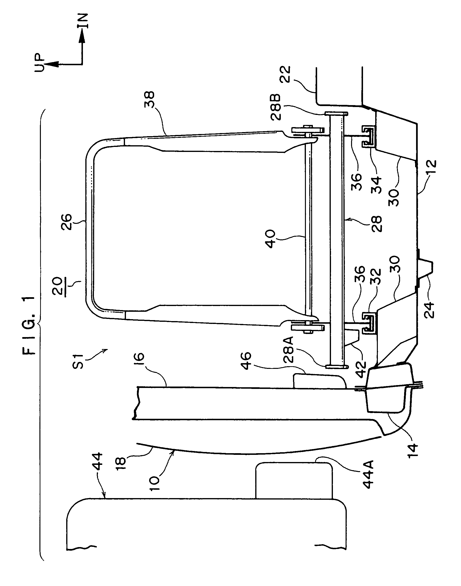
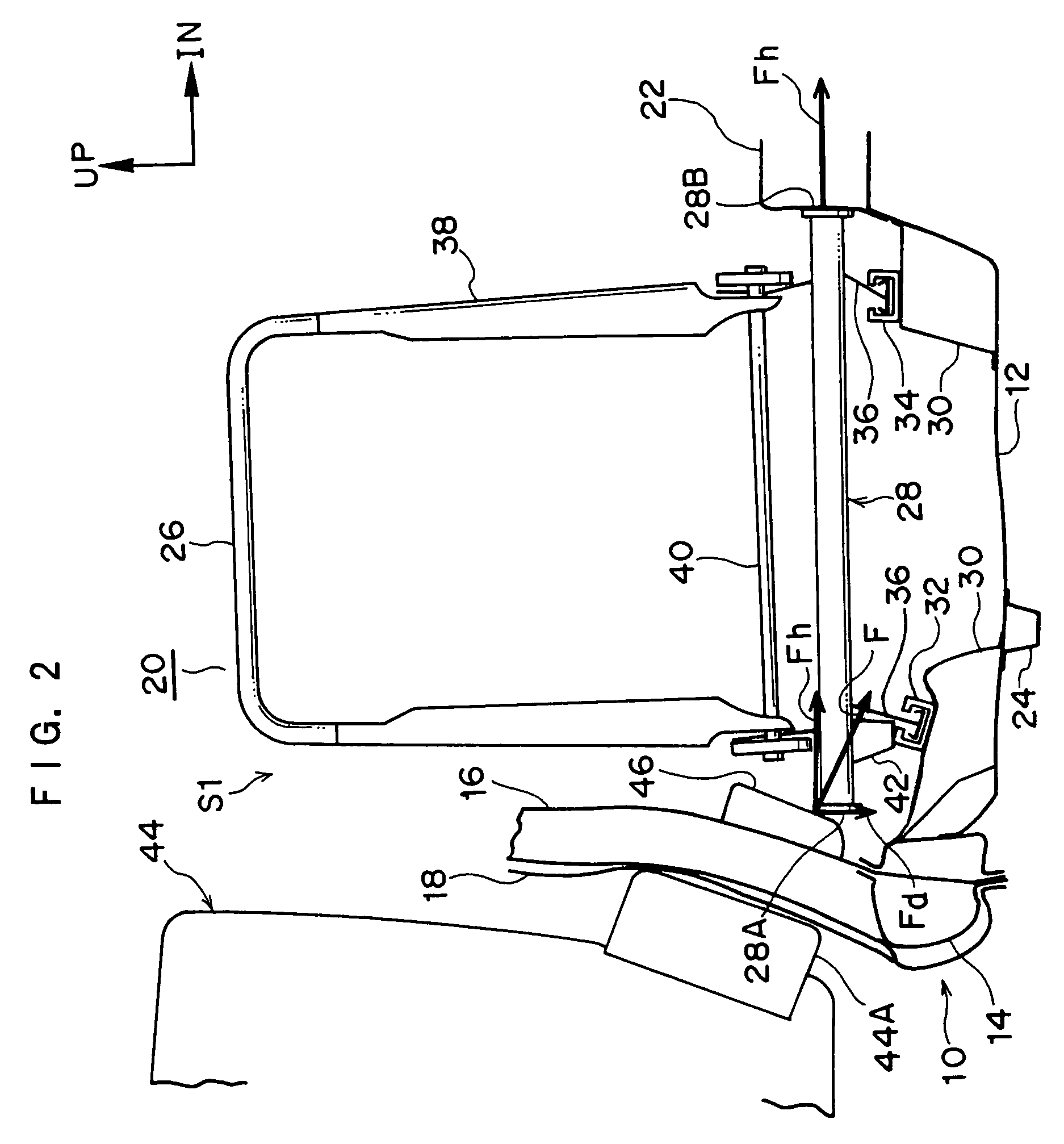
[0043]In FIG. 1, a vehicle body 10 includes a floor panel 12, a locker 14 disposed on a vehicle body side portion of the floor panel 12, a pillar 16 (e.g., a center pillar) disposed such that it rises upward from the locker 14, and an outer panel 18 of the vehicle body side portion. The area above the floor panel 12 in the vehicle body 10 serves as a cabin 20.

[0044]A tunnel portion 22, which is disposed such that it protrudes upward inside the cabin 20 and extends in the front-rear direction of the vehicle body 10, is formed in the substantial center of the floor panel 12 in the vehicle body width direction. An under-floor reinforcement 24 that extends in the vehicle body front-rear direction, for example, is disposed on the undersurface of the floor panel 12.

[0045]A side impact load transmitting structure S1 pertaining to the present embodiment includes a vehicular seat 26 (which will be referred to below simply as “the seat 26”; what is illustrated is the seat frame) disposed insi...

second embodiment

[0062]In FIG. 3, a side impact load transmitting structure S2 pertaining to a second embodiment of the invention includes, as a downward movement suppressing member, a stopper portion 50 (e.g., a retractor cover), which is disposed at the cabin 20 side of the pillar 16 (vehicle body side portion), and an engagement portion 48. The engagement portion 48 is disposed on the load transmitting member 28 and engages, only from above, with the stopper portion 50 when the pillar 16 is deformed at the time of a side impact collision and the stopper portion 50 ingresses into the cabin 20.

[0063]The stopper portion 50 is disposed such that it protrudes into the cabin 20 at a position substantially corresponding to the front surface of the load receiving portion 28A of the load transmitting member 28. It will be noted that the stopper portion 50 is not limited to protruding into the cabin 20 because it suffices as long as the stopper portion 50 is engageable with the engagement portion 48 of the...

third embodiment

[0071]In FIGS. 5 and 6, in a side impact load transmitting structure S3 pertaining to a third embodiment of the invention, a deformable engagement member 52 that is plate-like, for example, is disposed at the cabin 20 side of the pillar 16 (vehicle body side portion), and the same support member 42 as in the first embodiment is disposed on the load transmitting member 28. The load receiving portion 28A of the load transmitting member 28, which the deformable engagement member 52 contacts at the time of a side impact collision, is formed in an inclined manner, for example, such that it spreads more greatly than the diameter of the load transmitting member 28.

[0072]The deformable engagement member 52 has a plate thickness in the vehicle body width direction, has a width in the vehicle body vertical direction, and is spot-welded to the pillar 16 such that the deformable engagement member 52 covers a retractor 54 of a seat belt 56 attached to the inside of the pillar 16.

[0073]The height...


PUM


Abstract

A side impact load transmitting structure includes: a vehicular seat disposed in a cabin; a tunnel portion that is disposed such that it protrudes upward into the cabin and extends in a front-rear direction of a vehicle body; a load transmitting member including a load receiving portion that is disposed at the underside of the vehicular seat and receives a side impact load acting on a vehicle body side portion at the time of a side impact collision, with the load transmitting member being configured to transmit the side impact load received by the load receiving portion to the tunnel portion; and a downward movement suppressing member that suppresses the downward movement of the load transmitting member resulting from a downward load component of the side impact load.

Description

CROSS-REFERENCE TO RELATED APPLICATION[0001]This application claims priority under 35 USC 119 from Japanese Patent Application No. 2005-068117, the disclosure of which is incorporated by reference herein.BACKGROUND OF THE INVENTION[0002]1. Field of the Invention[0003]The present invention relates to a side impact load transmitting structure configured to transmit and receive, from a pillar and through a seat frame to a tunnel portion of a floor panel, a load acting on a vehicle body at the time of a side impact collision.[0004]2. Description of the Related Art[0005]Conventionally, as a structure that receives a load acting on a vehicle body at the time of a side impact collision, a structure has been disclosed which is configured to transmit a side impact load to a tunnel with a load direction deflecting member disposed on a seat, and where the load deflecting member and a pillar are fitted together at that time (e.g., see Japanese Patent Application Publication (JP-A) No. 2001-1304...

Claims


Application Information

Patent Timeline
Patent Type & Authority Patents(United States)
IPC IPC(8): B60N2/427B60N2/90
CPCB60N2/4235B60N2/42736B62D21/157B62D25/2036B62D25/025
Inventor MATSUDA, HIDENORI
Owner TOYOTA JIDOSHA KK
Why Eureka
Try Eureka