Clipped lens eyeglasses

a lens and eyeglass technology, applied in the field of eyeglasses and/or sunglasses, can solve the problems of requiring a relatively difficult special operation to be performed by qualified operatives using relatively expensive special tools, affecting the appearance of the frame, and affecting so as to achieve the effect of improving the stability of the fram

Inactive Publication Date: 2008-02-12
ESSILOR INT CIE GEN DOPTIQUE
View PDF8 Cites 8 Cited by
  • Summary
  • Abstract
  • Description
  • Claims
  • Application Information

AI Technical Summary

Benefits of technology

[0015]The object of the present invention is to provide an elegant solution to mounting lenses for eyeglasses quickly, providing both effective fastening of the lens to the frame, and a structure that is compact, enabling a frame to be of a refined shape.
[0016]To this end, the invention provides an eyeglasses frame with clipped lenses, the frame comprising a face structure provided with means for clipping to at least one lens, in which frame the means for clipping to at least one lens are arranged to operate by elastically clamping the lens, said clamping being exerted in a direction that is generally axial relative to the lens and in localized bearing zones, at least two of which are situated close to the edge of the lens and are angularly spaced apart from each other by at least 90° relative to the geometrical center of the edge of the lens. By means of the axial clamping performed in this way, it is possible to avoid any rim or other complex fitting or bolting system that is awkward to use without specialist tooling.
[0017]In an advantageous embodiment, the central bearing zone or stud is formed by an elastically flexible blade. This embodiment makes it possible to stiffen the horizontal strips of the frame by reserving the resilient return function to the wings formed by the blade. The wings are also capable of pressing against the rear face of the lens, fitting closely to part of its shape, thereby improving the effectiveness of the axial elastic clamping, and as a result improving the stability of the lens without damaging its surface state.

Problems solved by technology

Although those traditional mounting techniques generally give satisfaction from the point of view of positioning lenses accurately in front of the eye, they nevertheless present the major drawback of requiring a relatively difficult special operation to be performed by qualified operatives using relatively expensive special tooling.
Furthermore, mounting performed in that way is permanent and a lens can be replaced only by performing an operation that is just as complex and that lies outside the normal ability of a wearer of eyeglasses not specialized in the assembly thereof.
As a result, the cost of fitting and replacing lenses is relatively high.
The major drawback of that solution lies in the radial nature of the elastic clamping performed, since in order to hold the lens effectively it needs to be associated with the lens being surrounded in part by a rim, thus making the frame as a whole relatively bulky and unattractive in appearance.
Like the preceding solution, the frame proposed in that way is unattractive and / or restricted to half-glasses, insofar as it is ill-suited to mounting lenses of larger size.
Nothing is said about how the fitting is performed; in any event the fitting zone is unique for each lens, which makes mounting awkward to perform and not very reliable, in particular because of a lack of stability and rigidity.
That structure for eyeglasses is lacking in rigidity, in particular when the lens and the frame constituted solely by the temples and the bridge are all made of plastics material.
In addition the assembly is difficult to put together and can require the use of adhesive, which is unattractive in appearance and inconvenient.

Method used


Image

  • Clipped lens eyeglasses
  • Clipped lens eyeglasses
  • Clipped lens eyeglasses

Examples


first embodiment

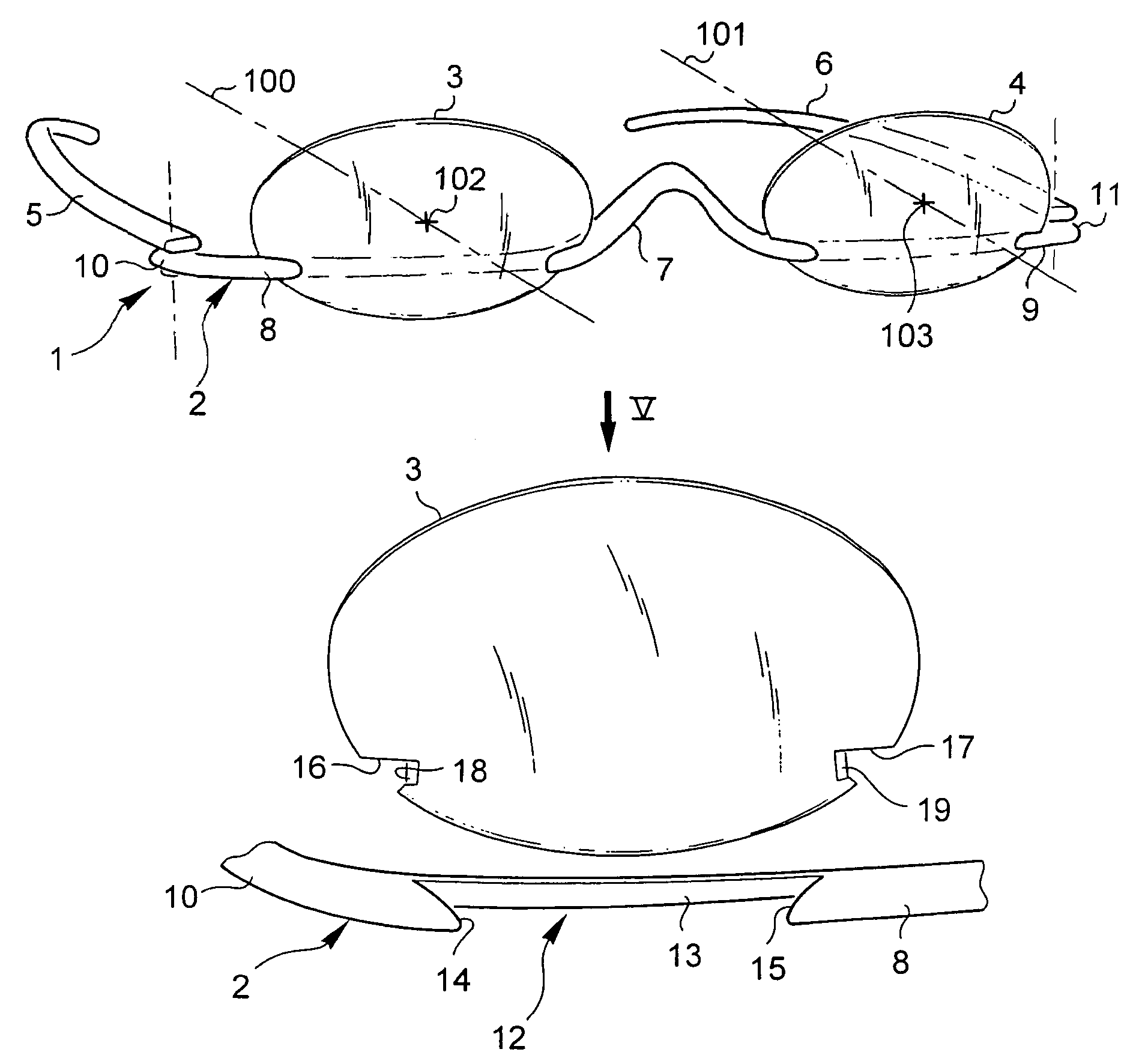
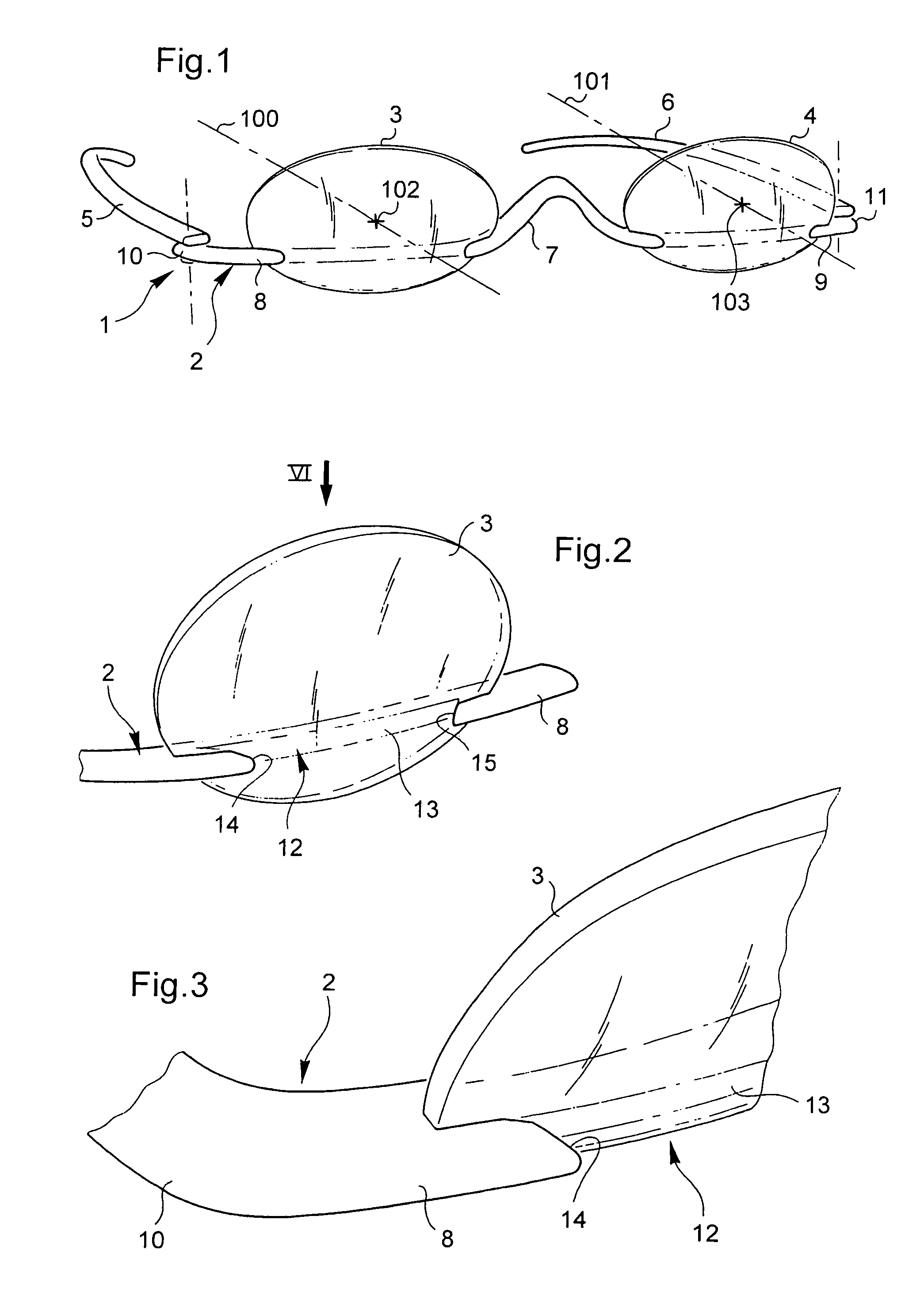
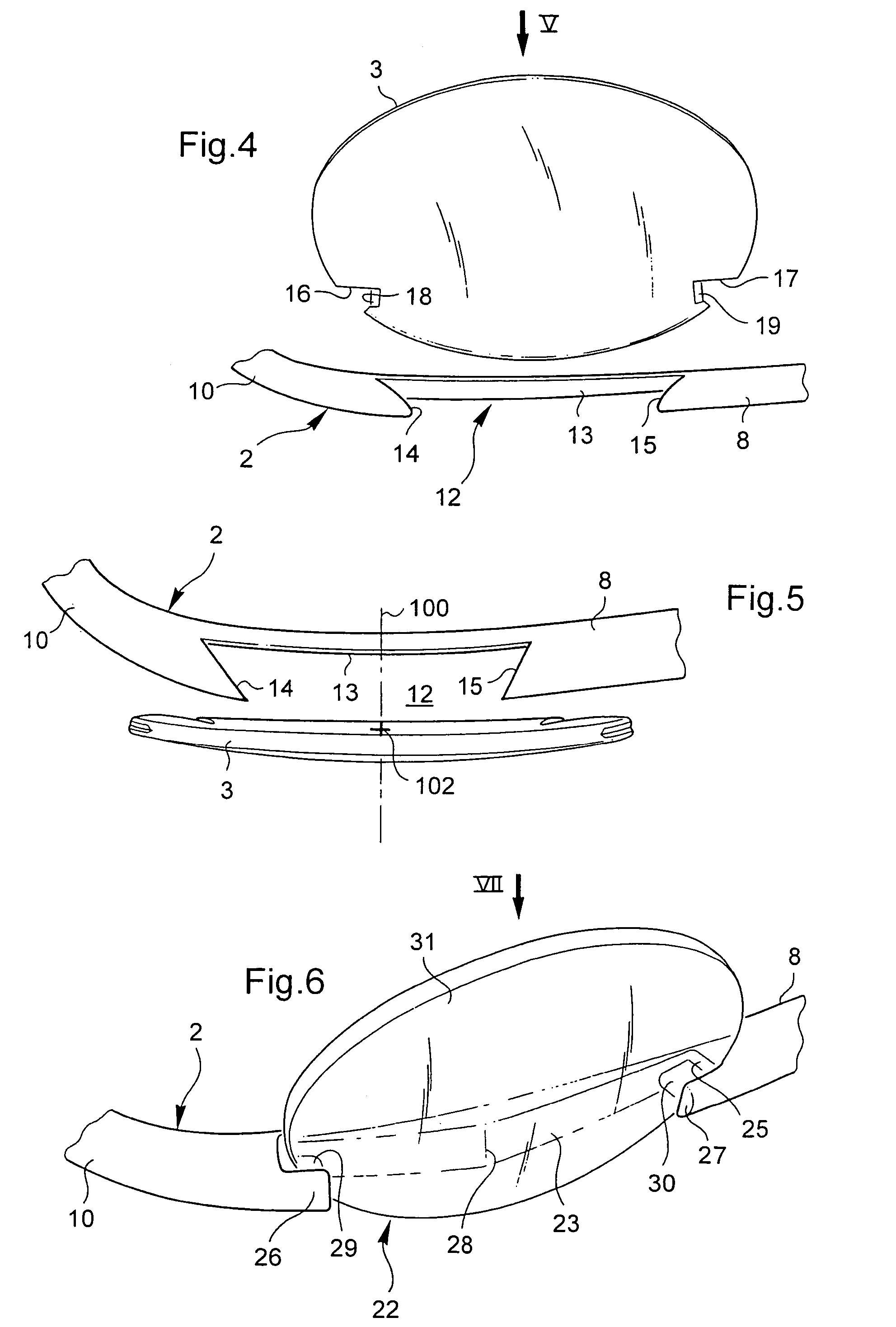
[0055]these means is shown in FIGS. 1 to 5. In order to receive the lens 3, 4 that is associated therewith, each of the two horizontal strips 8, 9 of the structure 2 presents a front lens-receiver notch 12. Along this receiver notch 12, each of the strips 8, 9 is curved longitudinally to match the curvature of the lens. The means for clipping the lens are arranged at the two side ends of the receiver notch.

[0056]The receiver notch 12 possesses two side ends 14, 15 arranged in undercut manner so that by virtue of their shape and their material, and in co-operation with the substantially rigid bottom 13 of the receiver notch 12, they constitute two resilient clamps that are V-shaped. Specifically, these two clamps constitute the means for clipping the corresponding lens 3, 4, and for this purpose they are arranged to apply axial resilient clamping thrust on the lens that is localized in two clamping zones situated in the vicinity of the edge of the corresponding lens 3, 4.

[0057]Becaus...

second embodiment

[0067]FIGS. 6 to 8 show eyeglasses in accordance with the invention.

[0068]The general architecture of the frame is similar to that of the frame 1 described above with reference to FIG. 1. As before, the two lenses are placed on either side of the bridge 7, and each of the two strips 8, 9 is provided with means for fastening the associated lens. In accordance with an essential characteristic of the invention, in order to ensure that the fastening of each lens is convenient and fast, the fastening is of the clipped type. In FIGS. 6 to 8 only the right strip 8 is shown together with an associated lens 31. The remainder of the general structure of the frame is analogous to that shown in FIG. 1, having two temples 5, 6 and a central bridge 7 for the nose interconnecting the two strips 8, 9. Only the means for clipping the lenses to the strips 8, 9 differ from those in the above-described first embodiment.

[0069]As before, these clipping means relate to the strips of the structure. Only th...

fourth embodiment

[0109]FIGS. 12 to 14 show the invention. A frame 81 comprises firstly a face structure 82 on which two lenses 83 are secured, and secondly two temples 85 for engaging the ears and hinged about vertical-axis hinges 86 to the side ends of the face structure 82. Only half of the frame is shown, with the other half being symmetrical thereto about a nasal midplane.

[0110]The face structure 82 has a central zone that possesses a bridge 87 for engaging the nose, the bridge presenting generally an upside-down V-shape, and the structure further possesses, symmetrically on either side of the bridge 87 and connected thereto, two horizontal strips 88 which are generally in alignment with each other.

[0111]In order to make it easier for the temples 85 to be hinged mechanically and in order to provide the frame with a certain amount of thickness for protecting the temples and the lenses, in particular when the temples 85 are folded against the frame 82, the strips 88 of the face structure 82 posses...


PUM


Abstract

The clip-lens eyeglasses frame includes a face structure provided with elements for clipping to at least one lens and arranged to operate by resiliently clamping the lens in a direction that is generally axial relative to the lens.

Description

TECHNICAL FIELD TO WHICH THE INVENTION RELATES[0001]The present invention relates in general to ophthalmic eyeglasses and / or sunglasses, and it relates more specifically to a frame for clipped lenses enabling the lenses to be mounted or replaced quickly, and it also relates to a quick-mount lens suitable for co-operating with such a frame.TECHNOLOGICAL BACKGROUND[0002]It is known that a pair of eyeglasses comprises two lenses that may be ophthalmic correcting lenses and / or sunglass lenses that are fitted to a frame which is designed to be placed on the wearer's nose in such a manner as to position one lens appropriately in front of each eye. Usually, the lenses are fixed permanently to the frame in a mounting operation.[0003]There exist several ways of mounting ophthalmic lenses. There are thus frames with rimmed lenses in which the frame typically comprises rims having the peripheral edges of the lenses fitted in edge-on after being cut out to the corresponding shape.[0004]There ar...

Claims


Application Information

Patent Timeline
Patent Type & Authority Patents(United States)
IPC IPC(8): G02C1/00G02C1/04
CPCG02C1/04G02C1/00G02B27/0176G02B2027/0156G02B2027/0178
Inventor ACTIS-DATTA, SEBASTIEN
Owner ESSILOR INT CIE GEN DOPTIQUE
Why Eureka
Try Eureka