Liquid cosmetic case

a cosmetic case and liquid technology, applied in the field of liquid cosmetic cases, can solve the problems of not being able to restore the original state of the tube-shaped container, not being able to carry or store safely, and not being able to easily releas

Inactive Publication Date: 2008-02-12
BYUN YOUNG KWANG
View PDF2 Cites 2 Cited by
  • Summary
  • Abstract
  • Description
  • Claims
  • Application Information

AI Technical Summary

Benefits of technology

[0008]In order to solve the above-described problems, it is an object of the present invention to provide a cosmetic case in which a discharger with a brush is coupled on the opening formed at the central upper part of a tube-shaped container, and a non-return valve is formed at one upper side of the tube-shaped container along with the coupled cap, so that when pressed, only a necessary amount of liquid cosmetic is discharged through the discharger for easy use and at the same time, when the pressing at the tube-shaped container is released, the non-return valve formed at one side of the tube-shaped container makes the tube-shaped container to be easily restored, so that the pressing on the tube-shaped container can be easily repeated, and the liquid cosmetic is easily discharged for convenient use.

Problems solved by technology

But in this kind of liquid cosmetic container, the tube-shaped container is often pressed carelessly, and the liquid cosmetic leaks, so that it is not easy to carry or to safely keep them.
However, this liquid cosmetic container is inconvenient in that as the discharge of liquid cosmetic through the liquid guiding passage and the discharge hole formed at the discharger is repeated, the liquid cosmetic can be stuck on the liquid guiding passage or the discharge hole or even can block the passage, then the contracted tube-shaped container cannot be restored to the original state, and the press and the release cannot be done easily so that a user cannot easily make up.

Method used


Image

  • Liquid cosmetic case
  • Liquid cosmetic case
  • Liquid cosmetic case

Examples


Embodiment Construction

[0016]Hereinafter, preferred embodiments of the present invention will be described with reference to the accompanying drawings.

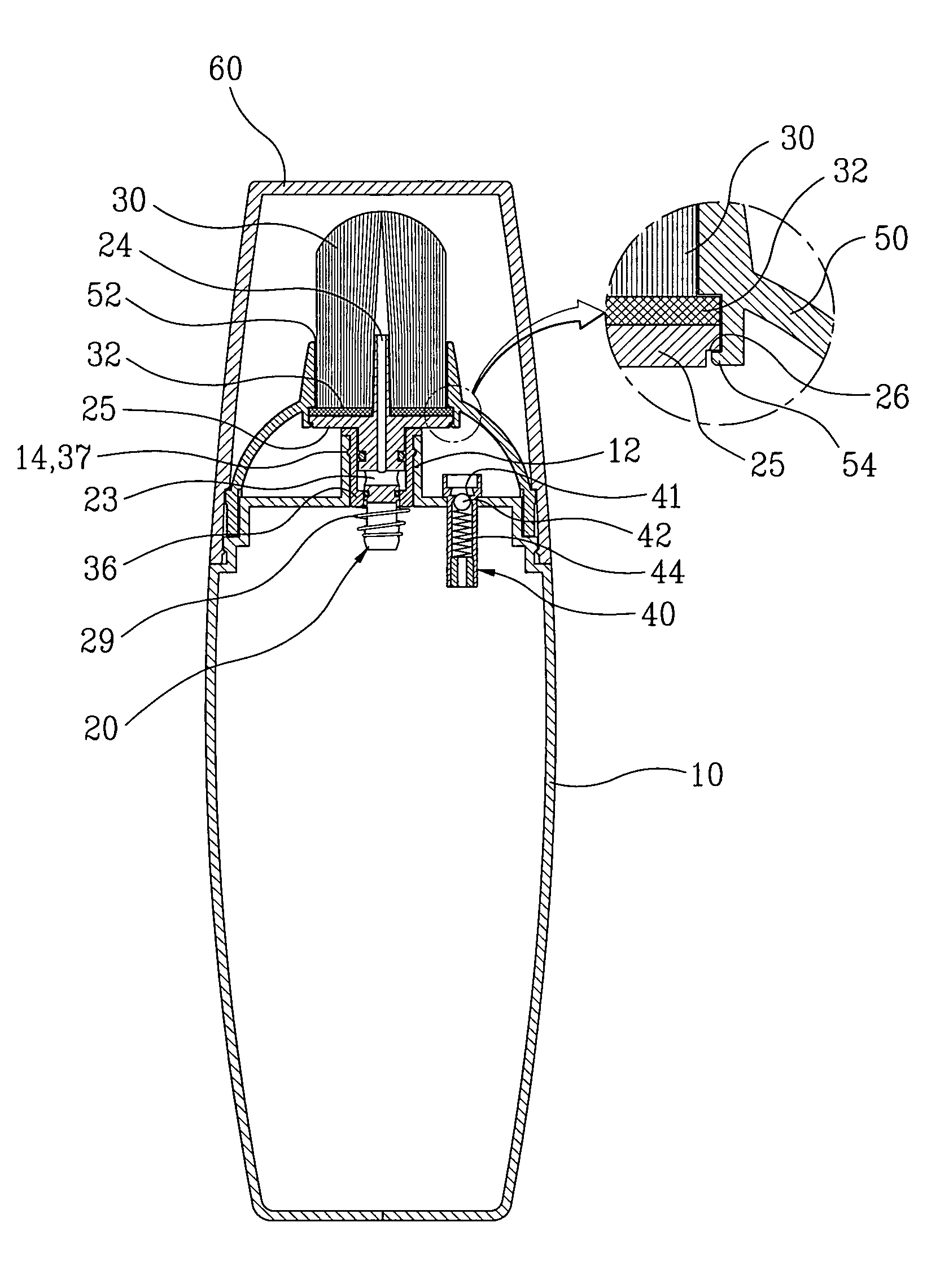
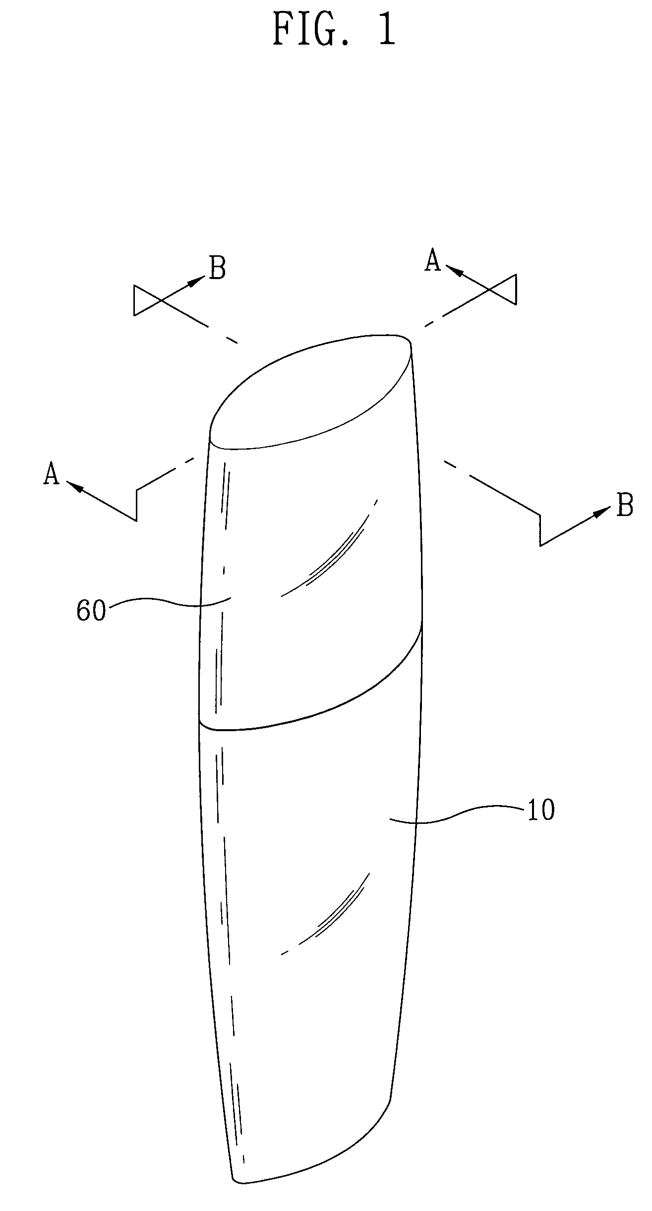
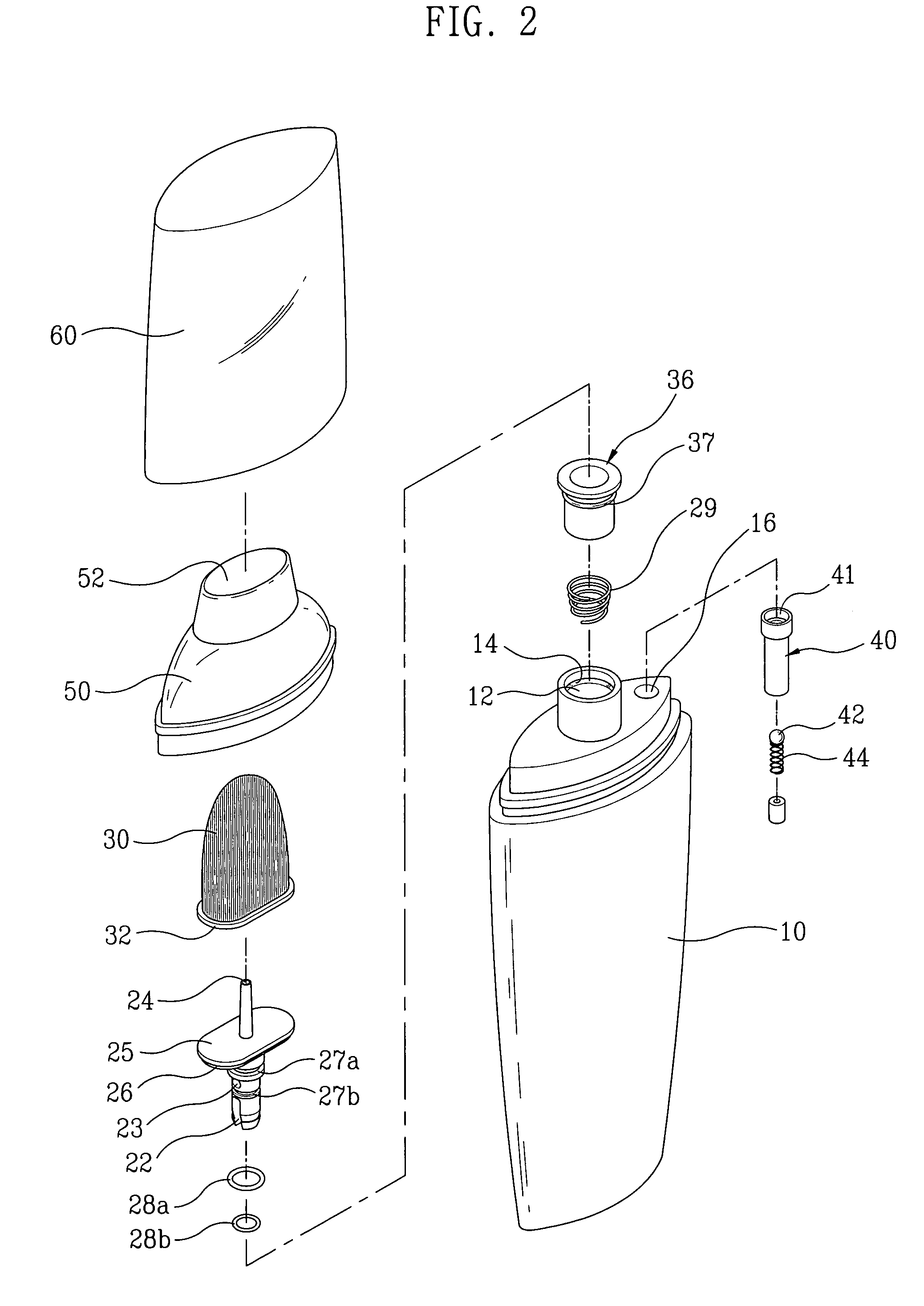
[0017]FIG. 1 is a perspective view of a cosmetic case according to the present invention, FIG. 2 is an exploded perspective view of the cosmetic case according to the present invention, FIG. 3 is a sectional view by A-A line of the cosmetic case according to the present invention, FIG. 4 is a sectional view by B-B line in the state a tube-shaped container is pressed according to the present invention, FIG. 5 is a sectional view of a non-return valve in the state a tube-shaped valve is pressed according to the present invention, and FIG. 6 is a sectional view of a non-return valve in the state the pressure on a tube-shaped valve is released according to the present invention.

[0018]According to the present invention, an opening 12 formed at the central upper part of a tube-shaped container 10 is coupled with a discharger 20 with a brush 30, and at the same ti...


PUM


Abstract

A liquid cosmetic case includes a discharger (20) which discharges and seals liquid cosmetic by having a brush (30) at the upper side of a tube-shaped container (10), a supporting cap (50) and a cap (60) by forming a non-return valve (40) at one side of the upper part of the tube-shaped container (10). When used, if the tube-shaped container (10) is pressed, only a necessary amount of liquid cosmetic is discharged through the discharger (10) for easy use, and if the press is released by the non-return valve (40) formed at one side of the tube-shaped container (10), as the valve hole (41) formed at the non-return valve (40) is opened and closed, the air flows into the tube-shaped container (10) or the air is blocked, so that the contraction and the restoration of the tube-shaped container (10) can be done easily, making the repeated presses of the tube-shaped container (10) easy and the use of liquid cosmetic easy.

Description

CROSS-REFERENCE TO RELATED APPLICATIONS[0001]This application claims the benefit of Korean Patent Application No. 10-2005-0023576, filed on Mar. 22, 2005, in the Korean Intellectual Property Office, the disclosure of which is incorporated herein by reference.BACKGROUND[0002]1. Field of the Invention[0003]The present invention relates to a liquid cosmetic case in which the upper side of a tube-shaped container includes a brush. Liquid cosmetic is discharged from the upper side, a sealing-structured discharger is coupled, and at the same time, a cap is coupled in a way that a non-return valve is formed at one side of the upper part of the tube-shaped container. If the tube-shaped container is pressed, a necessary amount of liquid cosmetic is discharged through a discharger for easy use. When the pressing on the tube-shaped container is released the non-return valve formed at one side of the tube-shaped container makes it easy for the tube-shaped container to be restored to its origina...

Claims


Application Information

Patent Timeline
Patent Type & Authority Patents(United States)
IPC IPC(8): A46B11/04B43M11/06
CPCA45D34/042A46B11/0041A45D34/043A46B2200/1046B65D85/14A45D2200/054A45D2034/002
Inventor BYUN, YOUNG-KWANG
Owner BYUN YOUNG KWANG
Why Eureka
Try Eureka