
Method and apparatus for rapid local oscillator frequency calibration

a local oscillator and frequency calibration technology, applied in the direction of oscillation generators, pulse automatic control, resonance circuit tuning, etc., can solve the problems of affecting the time required for a precision change in the frequency of the oscillator, substantial implementation and manufacturing complexity of the implementation expensive or otherwise impractical design of the vco controller, etc., to achieve quick and efficient selection of capacitors

Active Publication Date: 2008-02-12
TEXAS INSTR INC
View PDF2 Cites 9 Cited by
  • Summary
  • Abstract
  • Description
  • Claims
  • Application Information

AI Technical Summary

Benefits of technology

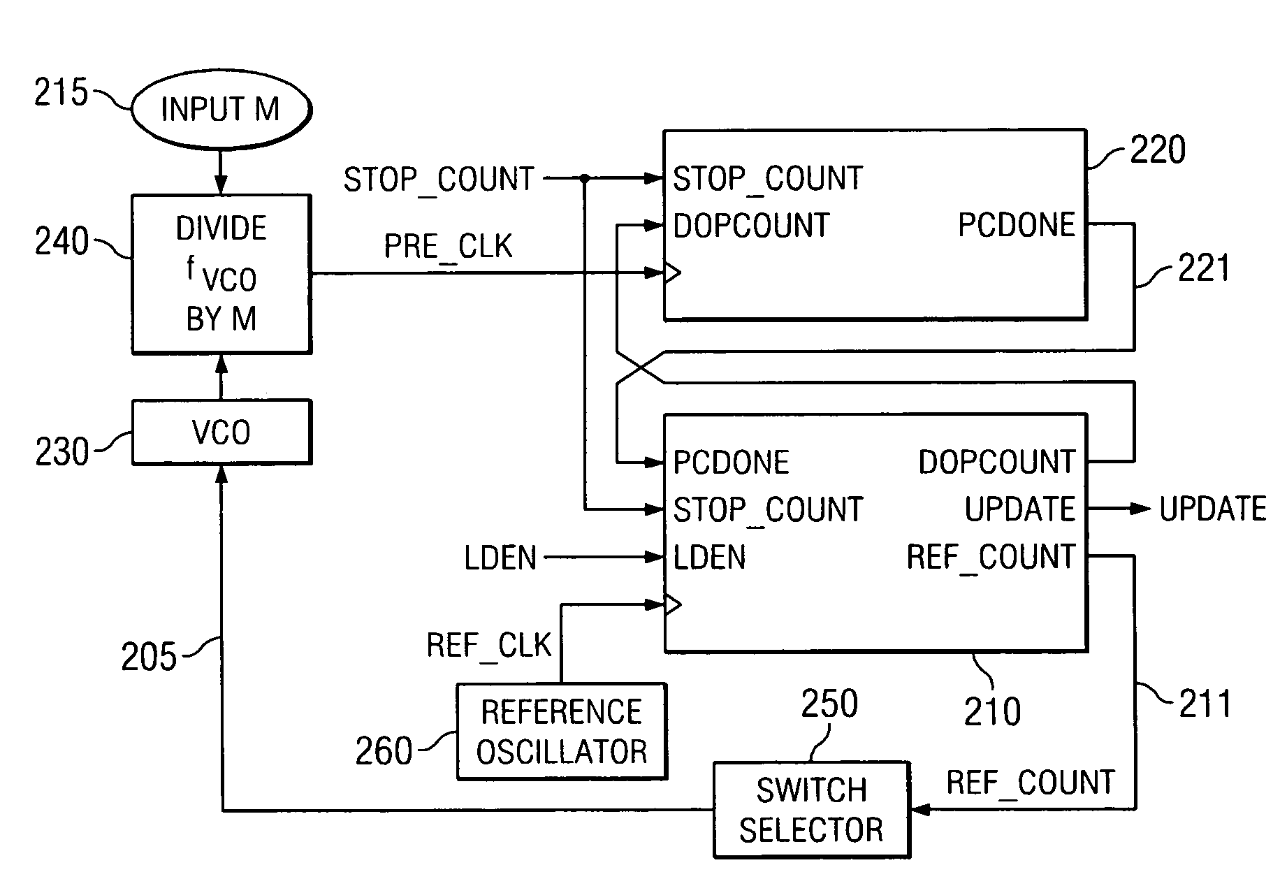
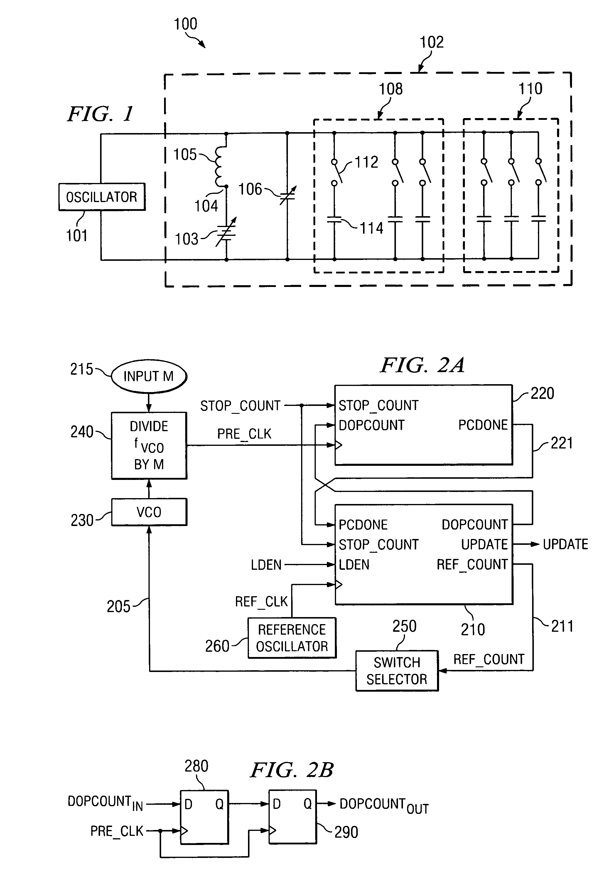
[0012]Preferred embodiments incorporating the invention solve the problem of quickly and efficiently selecting capacitors from a bank of capacitors to set the frequency of an adjustable-frequency oscillator to a desired frequency by counting oscillator cycles over a chosen interval of time. The signals to control switches that couple capacitors to a resonant tank circuit for the adjustable-frequency oscillator are determined from the count of oscillator cycles without the need for extended numerical computation.

Problems solved by technology

Control circuits of the prior art using digital processes for selection of resonant tank circuit tuning capacitors require extended numerical computation with substantial implementation and manufacturing complexity for their implementation.
Either approach uses significant die area for the circuit, resulting in a costly or otherwise impractical design for a VCO controller targeted at a broad commercial market.
In addition, the extensive computation required for capacitor selection adversely affects the time required for a precision change in oscillator frequency.
The main limitations of the prior art circuits are devices implemented with complex or slow processes to control the frequency of an adjustable-frequency oscillator.

Method used


Image

  • Method and apparatus for rapid local oscillator frequency calibration
  • Method and apparatus for rapid local oscillator frequency calibration
  • Method and apparatus for rapid local oscillator frequency calibration

Examples


Embodiment Construction

[0020]The making and using of the presently preferred embodiments are discussed in detail below. It should be appreciated, however, that the present invention provides many applicable inventive concepts that can be embodied in a wide variety of specific contexts. The specific embodiments discussed are merely illustrative of specific ways to make and use the invention, and do not limit the scope of the invention.

[0021]Embodiments of the present invention will be described with respect to preferred embodiments in a specific context, namely an apparatus and method using an input digital signal representing a desired frequency of an adjustable-frequency oscillator to selectively switch capacitors from a bank of capacitors into a resonant tank circuit coupled to the adjustable-frequency oscillator to control the oscillator frequency. Alternative embodiments comprise a computational process to control the frequency of a adjustable-frequency oscillator that avoids the need for numerical mu...


PUM


Abstract

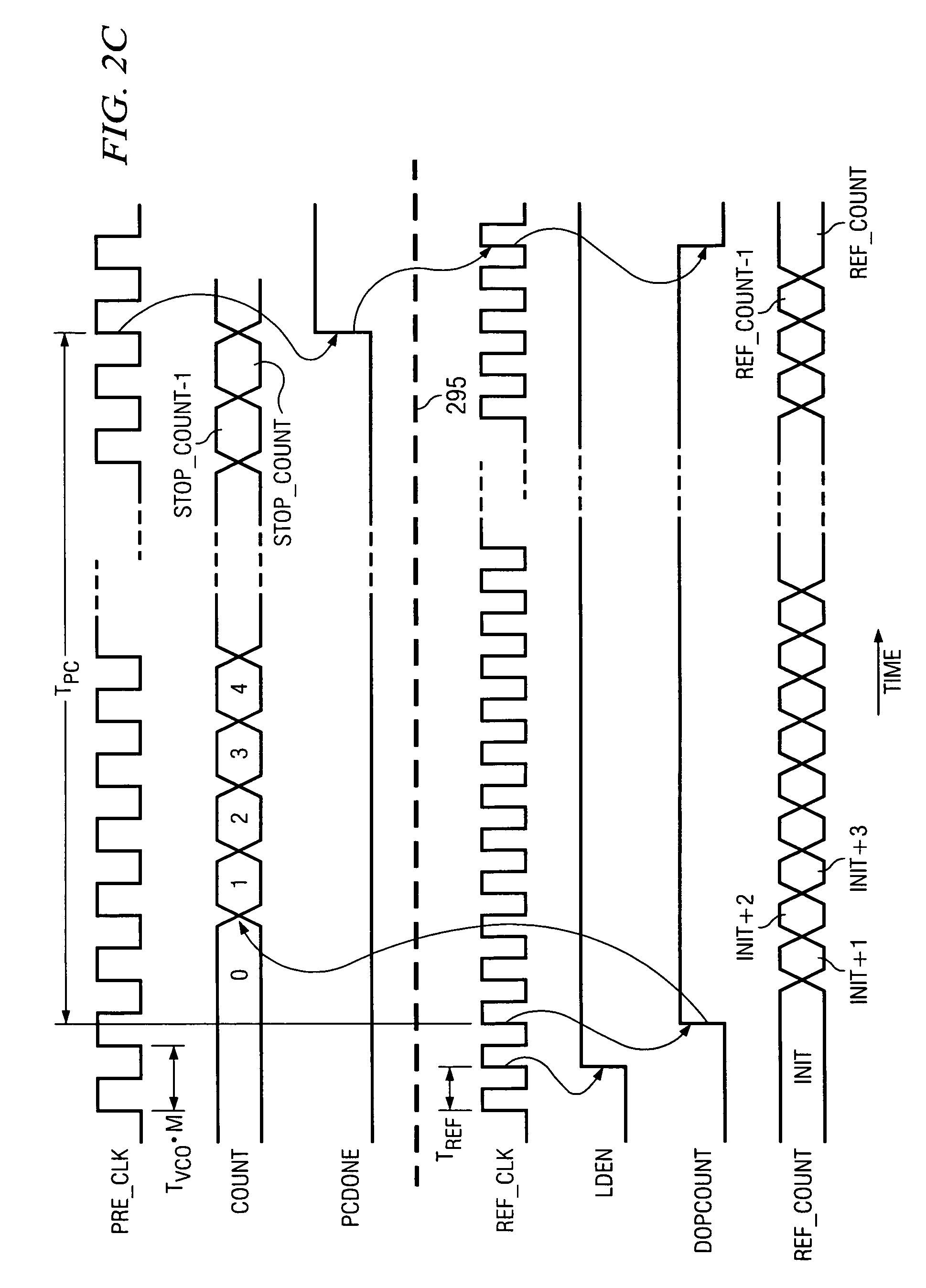
A controller for an adjustable-frequency oscillator includes a first counter supplied with a stop-count value to count adjustable-frequency oscillator cycles divided by the ratio of desired frequency to reference oscillator frequency, to produce a stop signal when the first counter reaches the stop-count value. A second counter counts cycles of a reference oscillator starting from an initial number related to the stop-count value. The second counter stops counting and produces an end-count when the second counter receives the stop signal from the first counter. A resonant tank circuit includes a bank of capacitors with switches to select resonant tank circuit capacitors. The switches are selectively controlled using the end-count in the second counter. The stop-count value is set for the first counter so that the end count number in the second counter using a ones-complement binary format can be used to iteratively set the switches with minimal digital computation.

Description

TECHNICAL FIELD[0001]This invention relates generally to adjustable-frequency oscillators and in particular, to a method and implementation for selecting switched capacitors to adjust the frequency of an adjustable-frequency oscillator.BACKGROUND[0002]Local oscillators are used in radio-frequency (RF) transmitters and receivers and in other applications to produce an adjustable-carrier or heterodyning frequency. An oscillator with an adjustable frequency enables a transceiver to communicate over a chosen channel. The local oscillator is generally implemented as a voltage-controlled oscillator (VCO) so that its frequency can be adjusted by a variable applied voltage. VCOs are generally implemented with a resonant tank circuit using a fixed inductor and a capacitor that is controlled with a voltage. Varactor diodes can be used to provide a voltage-controlled capacitance, which are back-biased semiconductor diodes wherein their junction depth and internal stored charge in the semicondu...

Claims


Application Information

Patent Timeline
Patent Type & Authority Patents(United States)
IPC IPC(8): H03L7/08
CPCH03L7/085H03L7/099H03B2201/025H03J2200/10H03L7/1976
Inventor WILLIAMS, III, LOUIS ALBERTCAVALIERE, FRANCESCO
Owner TEXAS INSTR INC
Learn More