
Image display device and image display method

Inactive Publication Date: 2008-02-12
SHARP KK
View PDF5 Cites 12 Cited by
  • Summary
  • Abstract
  • Description
  • Claims
  • Application Information

AI Technical Summary

Benefits of technology

[0039]The present invention was made in view of the foregoing problems, and it is an object of the present invention to provide an image display device and an image display method that are capable of preventing display flicker, which may be caused due to saturation of human visual perception with respect to changes in gradation and illuminance level of the display.
[0044]That is, in changing gradations by refreshing images per frame in the display panel, the output that was generated according to the last frame image is referred to in addition to the video signal, so as to suitably generate an output signal in conformity with the human perception, by taking into account saturation of the human visual perception. The output of the light source is controlled by the output signal so obtained. In this way, display flicker can be suppressed.
[0045]For example, the “bright black display” phenomenon, which may occur when a dark image is displayed, can be suppressed by conforming to the human visual characteristics, thereby displaying a high-contrast and high-quality image.
[0051]The present invention therefore provides an image display device that can limit display flicker, which may be caused due to saturation of human visual perception with respect to changes in gradation and illuminance level of the display.

Problems solved by technology

This increases the likelihood of display flicker when the display changes, for example, from bright display to dark display.
As a result, the displayed image does not change smoothly, and, when a change in quantity of light is too large, flicker is caused, and in other cases, the “bright black display” phenomenon, in which a black scene appears too bright, may be caused in the display.
For example, display flicker may be caused when the same control is carried out for the display change from bright to dark and from dark to bright.
In this case, the displayed image does not match the human visual characteristics, and the observer fails to recognize the image properly.

Method used


Image

  • Image display device and image display method
  • Image display device and image display method
  • Image display device and image display method

Examples


Embodiment Construction

[0063]One embodiment of the present invention is described below.

[0064]An image display device 1 of the present embodiment processes an input video signal so as to display it on a liquid crystal panel that is provided as a display panel. The input video signal is used by the image display device 1, so that a light source projects light on the liquid crystal panel according to the input video signal.

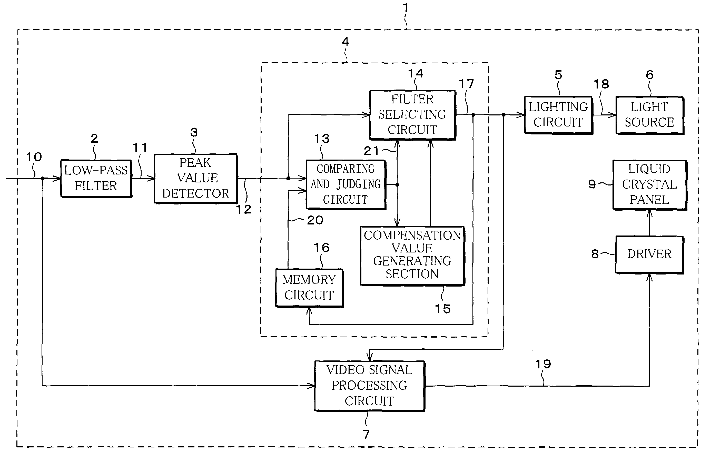
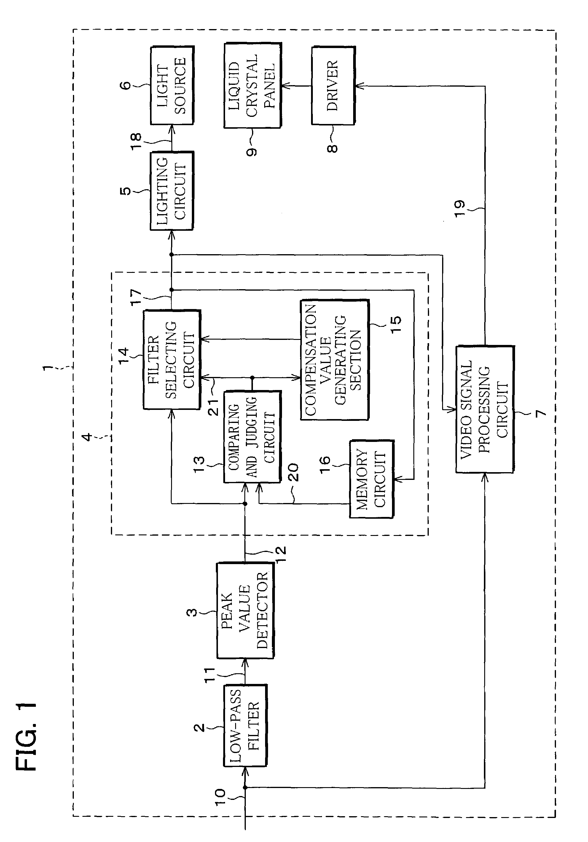
[0065]The image display device 1 includes a low-pass filter 2, a peak value detector 3, filter circuitry (light source control section) 4, a lighting circuit 5, a light source 6, a video signal processing circuit 7, a driver 8, and a liquid crystal panel (display panel) 9, as shown in FIG. 1.

[0066]The low-pass filter 2 is provided to remove a high-frequency component of a video signal 10 and outputs a low-pass filter output signal 11.

[0067]The peak value detector 3 detects and holds a peak value of the low-pass filter output signal 11, and outputs a peak value signal 12.

[0068]Here, as wil...


PUM


Abstract

An image display device controls the video signal and the lighting circuit according to the input video signal, so as to improve contrast, so that flicker or “bright black display”, which may be caused when the display characteristics do not match the human visual characteristics, is eliminated. The image display device includes a filter circuitry, in which a filter selecting circuit changes the filter characteristic according to the difference of a video signal and memory data stored in a memory circuit. The filter circuitry selects different filter characteristics for the display change from dark to bright and for the display change from bright to dark. This prevents display flicker, which may be caused due to saturation of human visual perception with respect to changes in gradation and illuminance level.

Description

FIELD OF THE INVENTION[0001]The present invention relates to an image display device and an image display method that display an input video signal on a display panel. The invention particularly relates to an image display device and an image display method that select an intensity of a light source according to the input video signal when projecting light onto the display panel displaying the video signal.BACKGROUND OF THE INVENTION[0002]One example of an image display device that displays an input video signal on a display panel such as a liquid crystal panel is disclosed in Japanese Publication for Unexamined Patent Application No. 65528 / 1999 (Tokukaihei 11-65528, published on Mar. 9, 1999).[0003]The image display device disclosed in this publication processes an input video signal and displays it on a liquid crystal panel. In addition, the light source projects light on the liquid crystal panel according to the input video signal.[0004]Referring to FIG. 8, a schematic structure ...

Claims


Application Information

Patent Timeline
IPC IPC(8): G09G3/36G02F1/133G09G3/20G09G3/34
CPCG09G3/3611G09G3/2014G09G2310/0275G09G2310/066G09G2320/0247G09G2320/0653G09G2340/16
Inventor ITOH, MOTOMITSUMUKAI, KAZUNORI
Owner SHARP KK
Learn More