
Control device of fuel system of internal combustion engine

a control device and fuel system technology, applied in the direction of electric control, liquid fuel feeders, machines/engines, etc., can solve the problems of insufficient fuel injection amount and vapor generation in the pipe, and achieve the effect of suppressing actuation sound and stable operation of the internal combustion engin

Inactive Publication Date: 2008-02-19
TOYOTA JIDOSHA KK
View PDF19 Cites 10 Cited by
  • Summary
  • Abstract
  • Description
  • Claims
  • Application Information

AI Technical Summary

Benefits of technology

The present invention provides a control device for a fuel system of an internal combustion engine that can suppress the actuation sound of the high-pressure fuel pump during idling of the engine and ensure stable operation of the engine. The control device detects the state of fuel in the pipe connecting the high-pressure pump and the fuel injection mechanism, and controls the high-pressure pump and low-pressure pump accordingly to prevent unstable combustion and vaporization of fuel. This results in stable fuel pressure and ensures proper fuel injection amount, suppressing the actuation sound of the high-pressure pump and allowing for stable engine operation.

Problems solved by technology

If the fuel is supplied to the fuel injection mechanism using the low-pressure pump instead of the high-pressure pump, however, vapors will be generated in the pipe when the fuel temperature is high, in which case a proper fuel injection amount may not be ensured.

Method used


Image

  • Control device of fuel system of internal combustion engine
  • Control device of fuel system of internal combustion engine
  • Control device of fuel system of internal combustion engine

Examples


Embodiment Construction

[0059]An embodiment of the present invention will be described hereinafter with reference to the drawings. The same elements have the same reference characters allotted. Their labels and functions are also identical. Therefore, detailed description thereof will not be repeated.

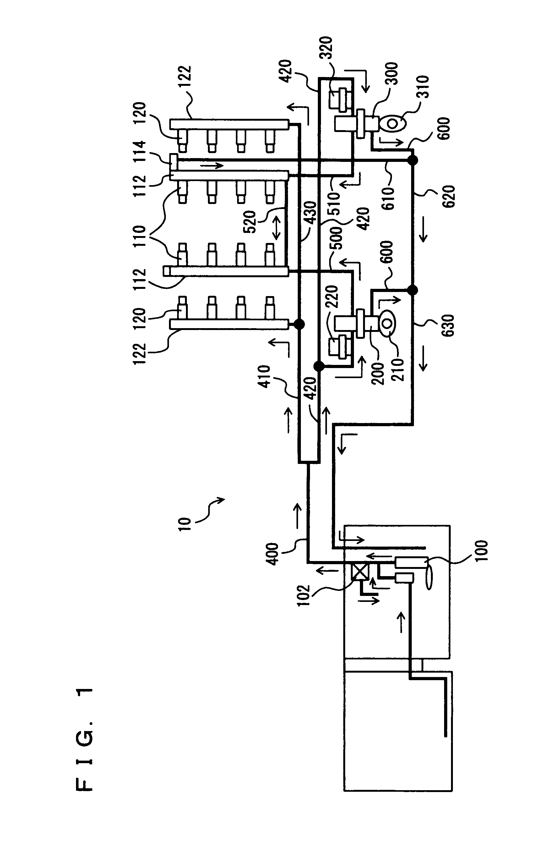
[0060]FIG. 1 shows a fuel supply system 10 of an engine controlled by an engine ECU (Electronic Control Unit) that is the control device according to an embodiment of the present invention. The engine is a V-type 8-cylinder gasoline engine, and has in-cylinder injectors 110 for injecting the fuel into the respective cylinders, and intake manifold injectors 120 for injecting the fuel into intake manifolds of the respective cylinders. It is noted that the present invention is not applied exclusively to such an engine, but is applicable to any engine having at least in-cylinder injectors 110 for injecting the fuel into the cylinders. It is also applicable to a gasoline engine of another type (including V-type 6-c...


PUM


Abstract

An engine control device executes a mechanism of controlling a fuel system during idling including the step of detecting an engine speed NE and an engine load, the step of determining whether fuel can be injected at normal feed pressure from an in-cylinder injector during idling, the step of detecting or estimating a fuel temperature T in a high-pressure delivery pipe, the step of stopping the high-pressure fuel pump and injecting fuel from the in-cylinder injector at the normal feed pressure when the fuel temperature T is not greater than T(0), the step of stopping the high-pressure fuel pump and injecting fuel at the pressure greater than the normal feed pressure when the fuel temperature T is greater than T(0) and not greater than T(1), and the step of driving the high-pressure fuel pump to inject the fuel at high pressure when the fuel temperature T is greater than T(1).

Description

[0001]This nonprovisional application is based on Japanese Patent Application No. 2005-197833 filed with the Japan Patent Office on Jul. 6, 2005, the entire contents of which are hereby incorporated by reference.BACKGROUND OF THE INVENTION[0002]1. Field of the Invention[0003]The present invention relates to a control device of a fuel system of an internal combustion engine that includes a fuel injection mechanism (in-cylinder injector) for injecting fuel into a cylinder at a high pressure, or an internal combustion engine that includes, in addition to the above fuel injection mechanism, another fuel injection mechanism (intake manifold injector) for injecting fuel into an intake manifold or an intake port. More particularly, the present invention relates to a technique of controlling the fuel system during idling of the internal combustion engine.[0004]2. Description of the Background Art[0005]An engine having a first fuel injection valve (in-cylinder injector) for injecting fuel in...

Claims


Application Information

Patent Timeline
Patent Type & Authority Patents(United States)
IPC IPC(8): F02B7/00F02B7/04
CPCF02D41/406F02M63/029F02M69/046F02D41/08F02D41/16F02D41/2422F02D2200/0602F02D2200/0606F02D2250/31Y02T10/44F02D41/3094F02D41/3845F02D2041/3881Y02T10/40
Inventor MASHIKI, ZENICHIRO
Owner TOYOTA JIDOSHA KK
Learn More