Rod retaining snap rod with enlarged retaining ring

a technology of retaining ring and snap rod, which is applied in the direction of conveying, packaging, transportation and packaging, etc., can solve the problems of not being able to disassemble without destroying the rod head, requiring tight tolerances of the diameter of the hole diameter of the outermost link and the diameter of the retaining ring, etc., to achieve the effect of less critical tolerance and increased shoulder siz

Active Publication Date: 2008-02-19
HABASIT AG
View PDF39 Cites 15 Cited by
  • Summary
  • Abstract
  • Description
  • Claims
  • Application Information

AI Technical Summary

Benefits of technology

[0007]The present invention meets the above-described need by providing a snap rod system such that the retaining ring can be made larger in order to increase the size of the shoulder which engages behind the link face. At the same time due to the larger ring diameter the bore of the outermost link needs to be enlarged accordingly in order to allow the larger retaining ring to be moved through the bore. Due to the larger difference between the retaining ring and the rod diameter, the tolerance becomes less critical. In one embodiment, the bore of the outermost link end is slightly eccentric in such a way that the enlarged shoulder of the retaining ring will be clearly overlapping the link face when assembled. When the belt is under tension the rod will be firmly forced into this retaining position, without losing the ability to transmit the belt pull.

Problems solved by technology

Rod retention can be accomplished by enlarging the heads of the pivot rods at both ends but such would not allow for disassembly without destroying the rod head.
In addition headless rods are often difficult to remove for disassembly.
The system described above has the drawback that it requires tight tolerances of the hole diameter of the outermost link and the retaining ring diameter.
In practice, there is a risk that the rod does not retain well enough or is retained tightly and cannot be easily disassembled.
In addition, if the retaining ring is a little too large, it may be sheared off when inserted.

Method used


Image

  • Rod retaining snap rod with enlarged retaining ring
  • Rod retaining snap rod with enlarged retaining ring
  • Rod retaining snap rod with enlarged retaining ring

Examples


Embodiment Construction

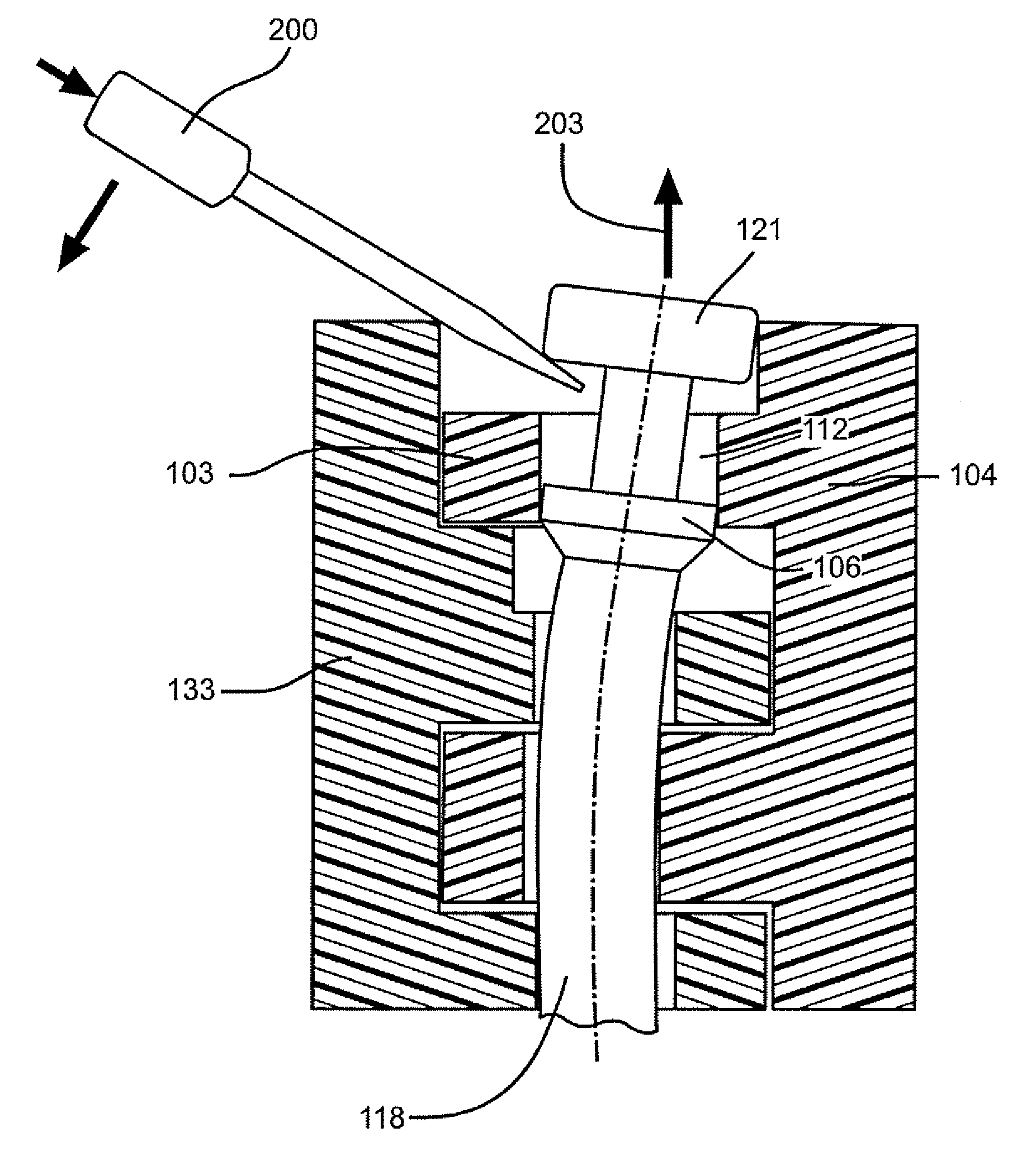
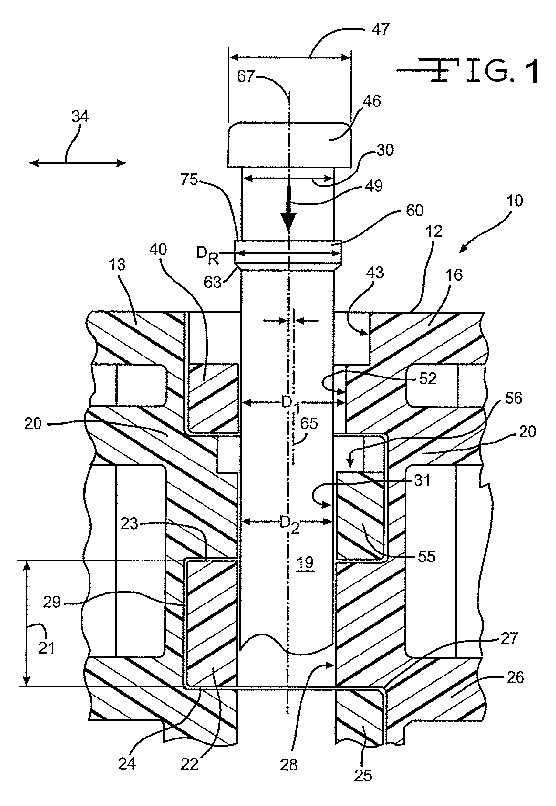
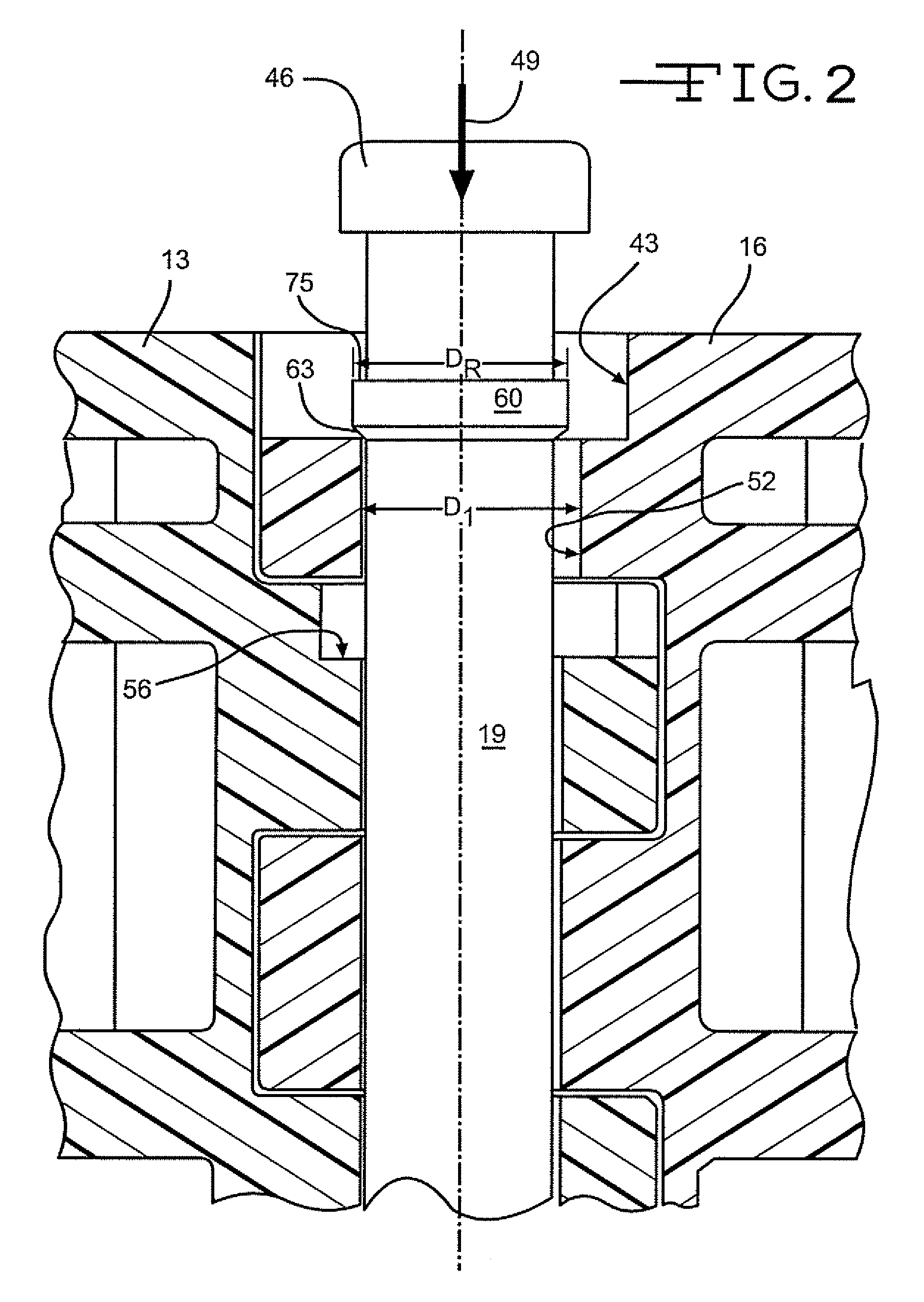
[0030]In FIGS. 1-4, a modular belt 10 is formed from a plurality of belt modules as will be evident to those of ordinary skill in the art. In FIG. 1, the outermost modules 13, 16 are shown. As will be evident to those of ordinary skill in the art, the belt 10 may be formed into varying widths in bricklayed fashion in a direction perpendicular to the direction of belt travel 34.

[0031]Each module 13, 16 has a module body 20 with a first and second plurality of link ends 22, 25 disposed in the middle of the module with respect to the outer edge 12 shown at the top of FIG. 1. Each link end 22, 25 has opposed side walls 23, 24 defining a first transverse thickness 21. The first transverse thickness 21 is connected to the intermediate section 26 of the module body 20 at a first proximal portion 27. The transverse thickness extends from the intermediate section 26 in a direction of belt travel to a first distal portion 29.

[0032]The link ends 22, 25 include openings 28, 31 disposed transver...


PUM


Abstract

A modular belt having modules intercalated and locked into position by a pivot rod having a retaining ring disposed in spaced apart relation relative to the end of the rod along the longitudinal axis. An outermost link end of the first plurality of link ends of the module has an opening that is larger in diameter and offset from the openings in the remaining link ends. The opening in the outermost link end may be substantially oblong-shaped with a portion of the opening coinciding with the remaining openings. The oblong shape improves the rod retaining function.

Description

CROSS-REFERENCE TO RELATED APPLICATION[0001]The present application is a continuation-in-part of U.S. patent application Ser. No. 10 / 891,807 filed Jul. 15, 2004, now U.S. Pat. No. 7,108,127 which claims priority to U.S. Provisional Patent Application No. 60 / 489,824 filed Jul. 24, 2003, entitled “Rod Retaining Snap Rod with Enlarged Retaining Ring,” which is incorporated herein by reference.FIELD OF INVENTION[0002]The present invention relates to modular conveying apparatus.BACKGROUND OF THE INVENTION[0003]Because they do not corrode, are light weight, and are easy to clean, unlike metal conveyor belts, plastic conveyor belts are used widely, especially in materials handling and conveying food products. Modular plastic conveyor belts are made up of molded plastic modular links, or belt modules, that can be arranged side by side in rows of selectable width. A series of spaced apart link ends extending from each side of the modules include aligned apertures to accommodate a pivot rod. ...

Claims


Application Information

Patent Timeline
Patent Type & Authority Patents(United States)
IPC IPC(8): B65G17/06B65G17/38B65G17/08B65G17/40B65G21/18
CPCB65G17/08B65G17/086B65G21/18B65G17/40B65G2207/12
Inventor KRISL, MICHALELSNER, DIETMAR
Owner HABASIT AG
Why Eureka
Try Eureka