
Bendable wing for micro air vehicle

a technology of micro air vehicles and fixed wings, which is applied in the field of micro air vehicles, can solve the problems of inability to lend themselves, rigid wings that cannot have their wing span reduced for storage, and micro air vehicles with fixed wings are often difficult to store, etc., and achieves convenient transportation, large space consumption, and sufficient stiffness.

Inactive Publication Date: 2008-02-19
UNIV OF FLORIDA RES FOUNDATION INC
View PDF8 Cites 19 Cited by
  • Summary
  • Abstract
  • Description
  • Claims
  • Application Information

AI Technical Summary

Benefits of technology

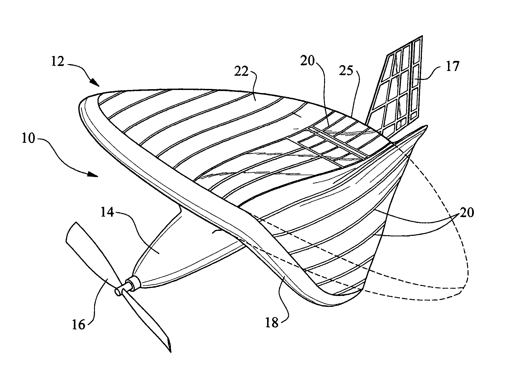
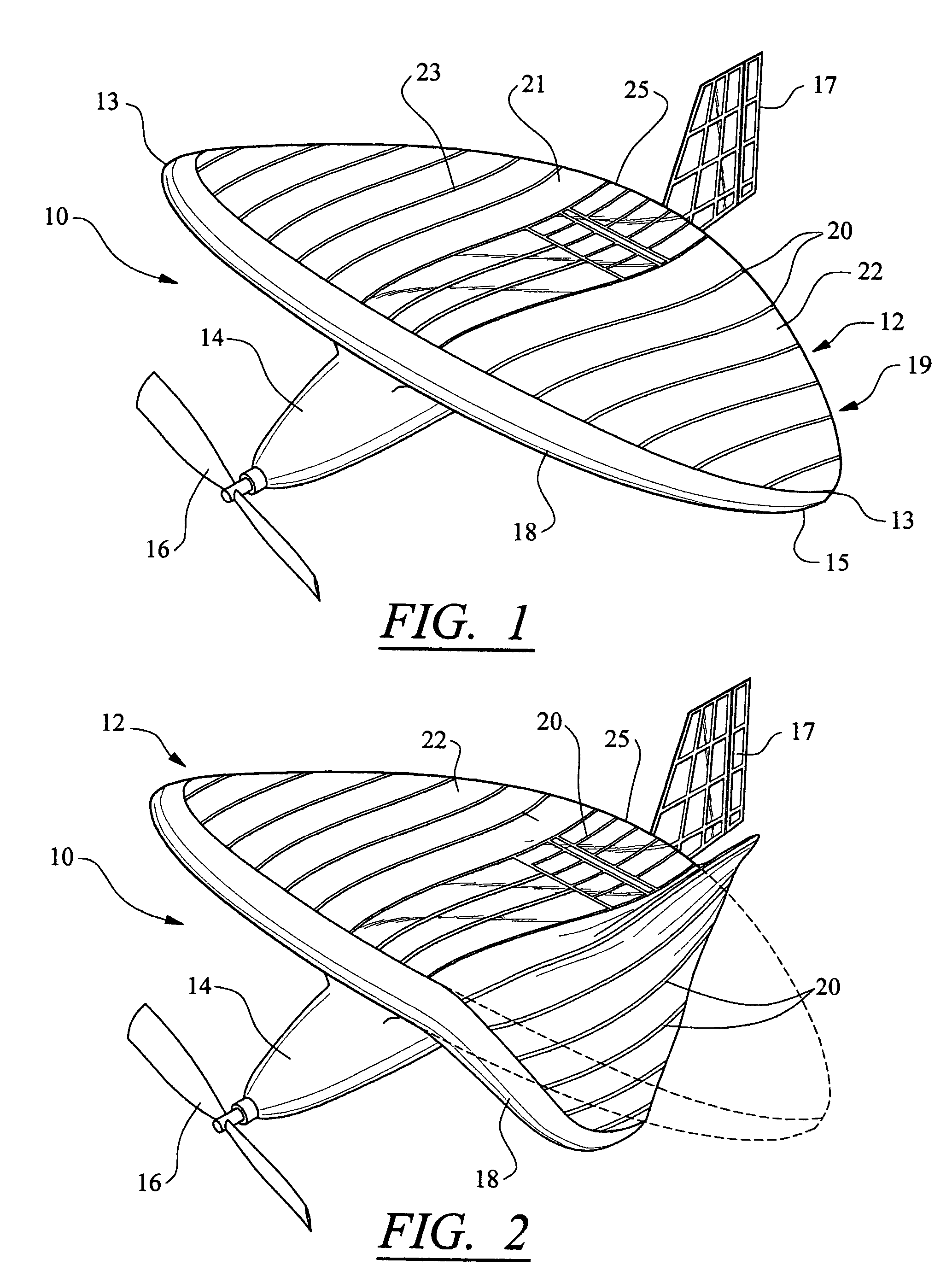
[0008]The wing may have a camber such that a bottom surface of the wing has a generally concave configuration when viewed parallel to a longitudinal axis of the wing. The camber may contribute to the stability of flight of a micro air vehicle to which the wing is attached and allow the wing to be bent downwards by not upwards. Thus, the wing may absorb and transfer uplift forces to the central body and allow the wing to be bent downward for storage.
[0011]An advantage of this invention is that a micro air vehicle incorporating the bendable wing of this invention may be stored in a small container and deployed without any actions taken to assemble the wings other than to release the tips from restraint. Releasing the wings enables the wings to return to the steady state position.
[0012]Another advantage of this invention is that the bendable wing has sufficient stiffness to absorb and transfer uplift forces to the body while enabling the wings to be bent downwardly for storage.
[0013]Yet another advantage of this invention is that by being able to be stored in such a small container, a micro air vehicle may be conveniently carried on a person, such as military personnel, without consuming much room.
[0014]Still another advantage of this invention is that the bendable wing may be produced relatively inexpensively.
[0015]Another advantage of this invention is that the wing is durable and capable of withstanding crash landings.

Problems solved by technology

Many micro air vehicles have fixed, rigid wings that are incapable of having their wing span reduced for storage.
Micro air vehicles having fixed wings are often difficult to store and do not lend themselves for storage in a knapsack or other item typically carried by military personnel in reconnaissance missions.
However, many of the micro air vehicles are inconvenient to be carried by military personnel because of their cumbersome wing span and shape.
Such requirements prevent these micro air vehicles from being deployed quickly and without human interaction.

Method used


Image

  • Bendable wing for micro air vehicle
  • Bendable wing for micro air vehicle
  • Bendable wing for micro air vehicle

Examples


Embodiment Construction

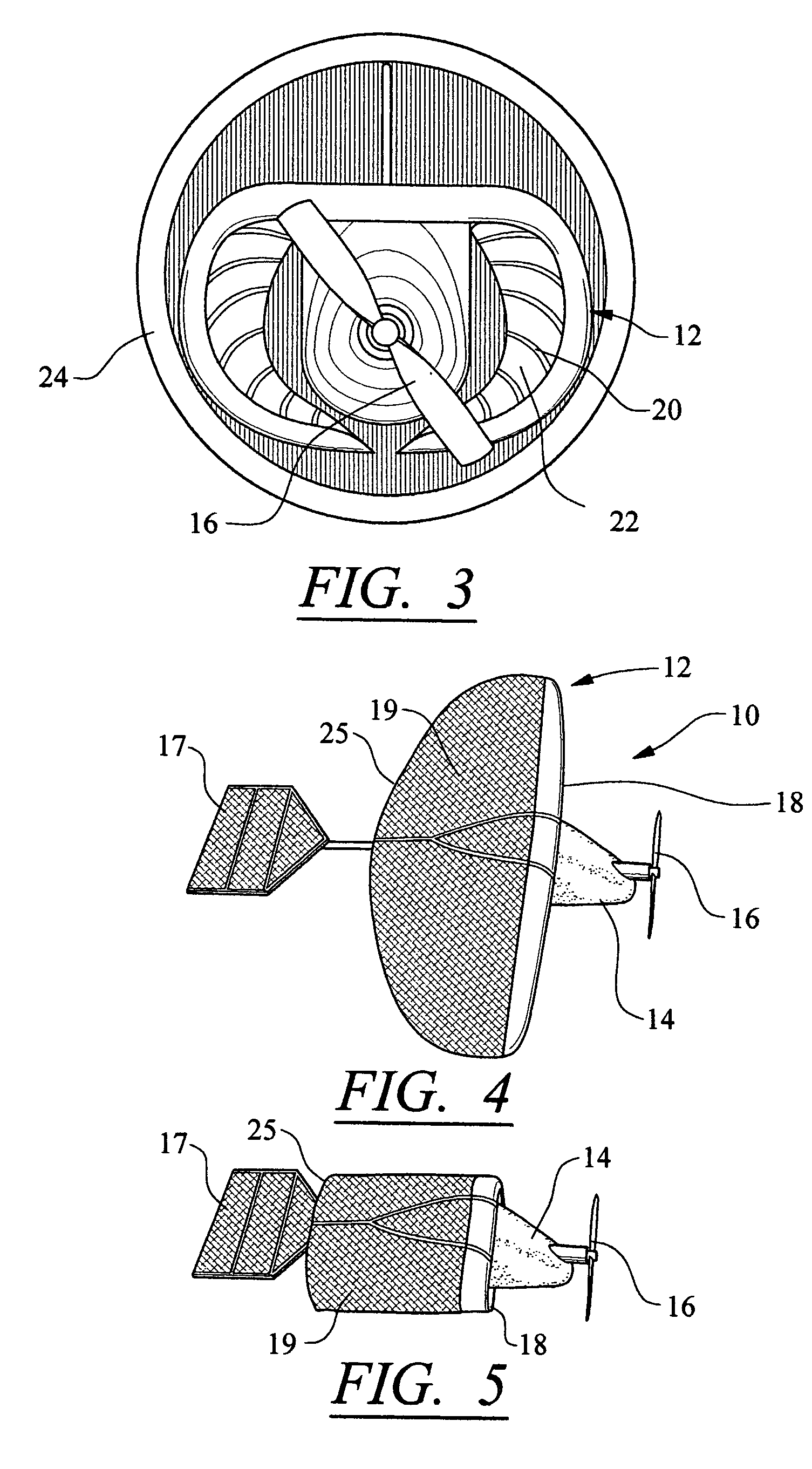
[0028]This invention is directed to a wing 12 for a micro air vehicle 10, as shown in FIGS. 1-10, that is bendable to enable the wing 12 to be easily stored in, for instance, a tube or other structure. The wing 12 may be attached to a body 14 that may or may not house an engine capable of providing rotational motion to a propeller 16. The engine may be, but is not limited to, one of many conventional engines used to power miniature aircraft. Body 14 may include a tail 17 for controlling the micro air vehicle 10. The tail 17 may be positioned generally orthogonal to the wing 12, as shown in FIGS. 1, 2, 8, and 10, generally parallel to the wing 12, as shown in FIGS. 4 and 5, or in another position. Micro air vehicle 10 may include other components that are typically found on miniature aircraft.

[0029]As shown in FIGS. 4 and 5, wing 12 may be formed one or more layers formed from resilient materials such that the wing 12 is bendable from a steady state position. The wing 12 may be bent ...


PUM


Abstract

A micro air vehicle having a bendable wing enabling the micro air vehicle to fly. The bendable wing may be bent downwards so that the wingspan may be reduced for storing the micro air vehicle. The bendable wing may be formed from one or more layers of material, and the wing may have a camber such that a concave surface of the wing faces downward. The wing may substantially resist flexing upwards and may transfer uplift forces to a central body of the micro air vehicle. In addition, the wing may be bent severely downwards by applying a force to tips of the wing. The micro air vehicle is capable of being stored in a small cylindrical tube and may be deployed from the tube by simply releasing the micro air vehicle from the tube.

Description

CROSS-REFERENCE TO RELATED APPLICATION[0001]This application is a divisional of U.S. patent application Ser. No. 10 / 731,777, filed Dec. 9, 2003 now abandoned , which claims the benefit of U.S. Provisional Application No. 60 / 431,920, filed Dec. 9, 2002.FIELD OF THE INVENTION[0002]This invention is directed generally to micro air vehicles, and more particularly, to wing configurations for micro air vehicles.BACKGROUND[0003]Micro air vehicles can trace their beginnings to model airplanes, which typically resemble full size airplanes. Micro air vehicles generally encompass all relatively small unmanned flying objects, such as those having wingspans less than about 36 inches. Micro air vehicles are often powered by small gasoline or electric propeller driven engines. Micro air vehicles are relatively lightweight vehicles capable of being used for a variety of purposes, such as for recreation, reconnaissance, and other purposes. Because of their small size, micro air vehicles lend themsel...

Claims


Application Information

Patent Timeline
Patent Type & Authority Patents(United States)
IPC IPC(8): B64C3/56A63H27/00B64C39/02
CPCA63H27/007B64C39/024B64C39/028B64C2201/021B64C2201/042B64C2201/044B64C2201/201B64C2201/082B64C2201/102B64C2201/123B64C2201/127B64C2201/165B64C2201/048B64U50/12B64U50/11B64U70/20B64U30/12B64U10/25B64U50/19B64U2101/30B64U50/13B64U80/70
Inventor IFJU, PETERLEE, KYU-HOALBERTANI, ROBERTOMITRYK, SHAWN J.BORIA, FRANK J.ABDULRAHIM, MUJAHID
Owner UNIV OF FLORIDA RES FOUNDATION INC
Learn More