Fuel-powered multi-rotor unmanned plane fuel supply scheme

A multi-rotor unmanned aerial vehicle, fuel-powered technology, which is applied to the fuel tank of the power unit, the fuel supply of the power unit, and the engine components, etc., can solve the problems of disorderly arrangement of fuel pipes, reduced space utilization, damage to fuel circuits or injectors, etc. , to reduce the maintenance workload, increase the flight stability, and ensure the safety of the oil circuit.

Active Publication Date: 2016-11-09
辽宁大壮无人机科技有限公司
View PDF6 Cites 13 Cited by
  • Summary
  • Abstract
  • Description
  • Claims
  • Application Information

AI Technical Summary

Problems solved by technology

[0002] At present, fuel-powered multi-rotors are not common. Existing fuel-powered multi-rotors usually use one engine to configure a fuel supply system. The disadvantages are high cost, heavy weight, and difficult maintenance; Simple mold opening production, no anti-shake and anti-sideflow measures, prone to tilt when the body is maneuvering, causing a certain engine to stop due to lack of fuel, and independent external hanging will reduce space utilization; some fuel-powered multi-rotors do not set fuel Pressure regulator, if the oil pressure is too low, the injector will not inject fuel or the fuel injection will be weak; if the oil pressure is too high, the oil circuit or injector will be damaged; Sticking and other methods to fix, the oil pipe arrangement is also particularly messy, easy to curl and produce air bubbles

Method used


Image

  • Fuel-powered multi-rotor unmanned plane fuel supply scheme
  • Fuel-powered multi-rotor unmanned plane fuel supply scheme
  • Fuel-powered multi-rotor unmanned plane fuel supply scheme

Examples


example 1

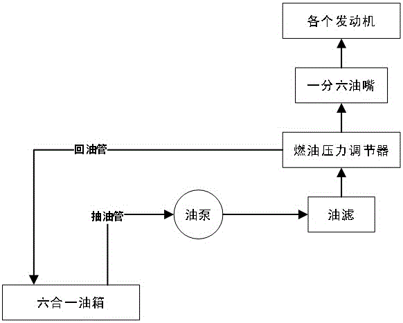
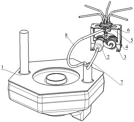
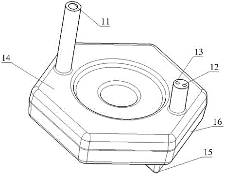
[0028] Such as figure 1 and 2 As shown, the oil-driven six-rotor fuel supply scheme consists of a six-in-one fuel tank 1, an oil pump 2, an oil filter 3, a fuel pressure regulator 4, one point six oil nozzles 5, a fixed support 6, an oil suction pipe 7 and an oil return pipe 8.

[0029] The six-in-one fuel tank 1 communicates with the oil pump 2 through the oil suction pipe, the oil pump 2 communicates with the oil filter 3, the oil filter 3 communicates with the one-point six oil nozzle 5 through the fuel pressure regulator 4, and the one-point six oil nozzle 5 communicates with each engine connected, the fuel pressure regulator 4 is connected to the six-in-one fuel tank 1 through the oil return pipe; the oil pump 2, the oil filter 3 and the one-point six oil nozzle 5 are screwed on the fixed support 6; the fixed support 6 is screwed On the fuselage; the fuel pressure regulator 4 is screwed on the fuel pressure regulator support 523 integrated with the one-point six oil nozz...

example 2

[0044] Such as Figure 8 Shown is the fuel supply scheme of the oil-driven four-rotor. Except for the use of one-point four-oil nozzles, the other structures are exactly the same as those described in Example 1. The one-point-four nozzle adopts the one-point-four design, that is, one oil inlet branches out to four oil outlets to ensure that only one oil filter, one oil pump and one fuel pressure regulator appear in the fuel supply system; the number of oil outlets is equal to that of the rotor quantity.


PUM


Abstract

The invention relates to a fuel-powered multi-rotor unmanned plane fuel supply scheme. An all-in-one fuel tank, a fuel pump, a fuel strainer, a fuel pressure regulator, a one-to-more nipple and a fixed support constitute a whole fuel supply system. The central idea of the scheme is all-in-one one-to-more combined design. The fuel tank adopts the all-in-one design: a plurality of partitions with smaller height than the fuel tank are arranged inside the fuel tank, and the upper and lower ends of each partition do not contact the upper and lower surfaces of the fuel tank, so that the whole fuel tank is divided into a plurality of independent small fuel tanks which communicate with each other. The nipple adopts the one-to-more design: one fuel inlet is divided into a plurality of fuel outlets. The fuel pressure regulator and the one-to-more nipple form an integral body, and do not need special arrangement. The scheme solves the following problems: fuel shortage of a certain engine can easily occurs when the fuel-powered multi-rotor unmanned plane is inclined, each engine of the fuel-powered multi-rotor unmanned plane needs one fuel supply system, bubbles can easily appear in the fuel supply system, and the fuel pressure regulator needs to be independently arranged.

Description

technical field [0001] The invention belongs to the technical field of unmanned aerial vehicles, and in particular relates to a fuel supply scheme for a fuel-powered multi-rotor unmanned aerial vehicle. Background technique [0002] At present, fuel-powered multi-rotors are not common. Existing fuel-powered multi-rotors usually use one engine to configure a fuel supply system. The disadvantages are high cost, heavy weight, and difficult maintenance; Simple mold opening production, no anti-shake and anti-sideflow measures, prone to tilt when the body is maneuvering, causing a certain engine to stop due to lack of fuel, and independent external hanging will reduce space utilization; some fuel-powered multi-rotors do not set fuel Pressure regulator, if the oil pressure is too low, the injector will not inject fuel or the fuel injection will be weak; if the oil pressure is too high, the oil circuit or injector will be damaged; Sticking and other methods to fix, the tubing layou...

Claims


Application Information

Patent Timeline
Patent Type & Authority Applications(China)
IPC IPC(8): B64D37/00B64D37/08F02M61/18
CPCB64D37/00B64D37/08F02M61/1806
Inventor 姜文辉陈浩郭向群张贺张永伟吕卉甘子东张奎文王子琦
Owner 辽宁大壮无人机科技有限公司
Why Eureka
Try Eureka