Fluid ejecting apparatus

a technology of ejecting apparatus and liquid, which is applied in the direction of printing, other printing apparatus, etc., can solve the problems of difficult to completely remove bubbles, poor discharge of ink droplets, and insufficient attention to the above problem

Inactive Publication Date: 2009-12-03
SEIKO EPSON CORP
View PDF28 Cites 13 Cited by
  • Summary
  • Abstract
  • Description
  • Claims
  • Application Information

AI Technical Summary

Benefits of technology

[0008]An advantage of some aspects of the invention is that it provides a technique for removing bubbles that cause poor ejection in nozzles of a fluid ejecting apparatus that ejects fluid.
[0009]A fluid ejecting apparatus that ejects fluid includes: a pressure chamber that is filled with the fluid; a pressure generating element that deforms a wall face of the pressure chamber to change a volume of the pressure chamber; a nozzle that is in fluid communication with the pressure chamber and that is used for ejecting the fluid; and a control unit that generates a drive pulse for controlling the pressure generating element. The control unit is able to generate a maintenance drive pulse for ejecting a bubble together with the fluid from the pressure chamber. The maintenance drive pulse includes a first pulse portion that drives the pressure generating element to cause the pressure chamber to expand into an expanded state and a second pulse portion that causes the pressure chamber to contract from the expanded state. The width of the second pulse portion is equal to or smaller than half the Helmholtz resonance period of the fluid with which the pressure chamber is filled. According to the above fluid ejecting apparatus, at the time of flushing, a pressure applied to fluid in the pressure chamber by the pressure generating element may be further increased using Helmholtz resonance. Then, it is possible to further increase a force, As a result of a pressure wave, that acts on fluid in the pressure chamber to further increase the speed at which a bubble disappears, while making it possible to discharge the bubble with the fluid. Thus, it is possible to reliably remove a bubble, which causes poor ejection in a nozzle, in the pressure chamber. Note that in the specification, the real numbers shown to the first decimal place have set one significant digit and are rounded off to the first decimal place.
[0010]In the fluid ejecting apparatus according to an embodiment of the invention, the width of the second pulse portion is equal to or larger than half the natural vibration period of the pressure generating element. According to the above fluid ejecting apparatus, a pressure may be applied to the fluid in the pressure chamber as it is resonated with the natural vibration of the pressure generating element. Thus, it is possible to further reliably remove a bubble in the pressure chamber.
[0011]In the fluid ejecting apparatus according to another embodiment of the invention, the maintenance drive pulse further includes an intermediate pulse portion between the first and second pulse portions, wherein the intermediate pulse portion holds the expanded state of the pressure chamber for a predetermined period of time, and the width of the intermediate pulse portion is equal to or larger than 0.7 times the Helmholtz resonance period of the fluid. According to the above fluid ejecting apparatus, the width of the intermediate pulse portion is adjusted in view of the Helmholtz resonance period of the fluid in the pressure chamber in order to make it possible to apply a pressure to the fluid in the pressure chamber by the second pulse portion at a timing at which a further large pressure may be generated. Thus, it is possible to further reliably remove a bubble in the pressure chamber.
[0012]In the fluid ejecting apparatus according to another embodiment of the invention, the width of the intermediate pulse portion is equal to or shorter than the Helmholtz resonance period of the fluid. According to the above fluid ejecting apparatus, it is possible to improve the nozzle recovery rate and also possible to improve the flight stability of discharged fluid. Thus, it is possible to suppress an increase in the amount of fluid consumed in discharging for nozzle recovery.
[0013]In the fluid ejecting apparatus according to another embodiment of the invention, the fluid ejecting apparatus ejects ink as the fluid. According to the above fluid ejecting apparatus, even when a bubble is generated in ink inside the pressure chamber, the bubble may be easily removed. Thus, it is possible to suppress occurrence of dot omission or ink clogging.

Problems solved by technology
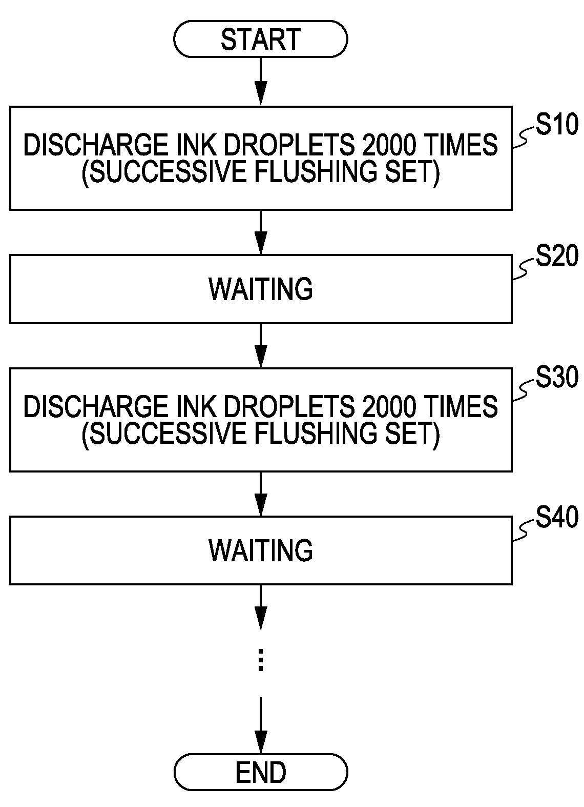
In the ink jet printer, because of thickened ink adhered to nozzle openings due to natural evaporation or absorption of pressure change in ink chambers by bubbles trapped in the ink chambers that are filled with ink, poor discharge of ink droplets may occur.
However, even when the above maintenance process has been performed, a sufficient force, such as pressure, for draining bubbles cannot be applied for micro-diameter bubbles (for example, bubbles having a diameter of several tens of micrometers), so that it is difficult to completely remove bubbles.
The above problem not only applies to an ink jet printer but also applies to a fluid ejecting apparatus that ejects fluid other than ink (including liquid and liquid body formed of dispersed particles of a functional material).
The above problem has not been addressed sufficiently.

Method used


Image

  • Fluid ejecting apparatus
  • Fluid ejecting apparatus
  • Fluid ejecting apparatus

Examples


Embodiment Construction

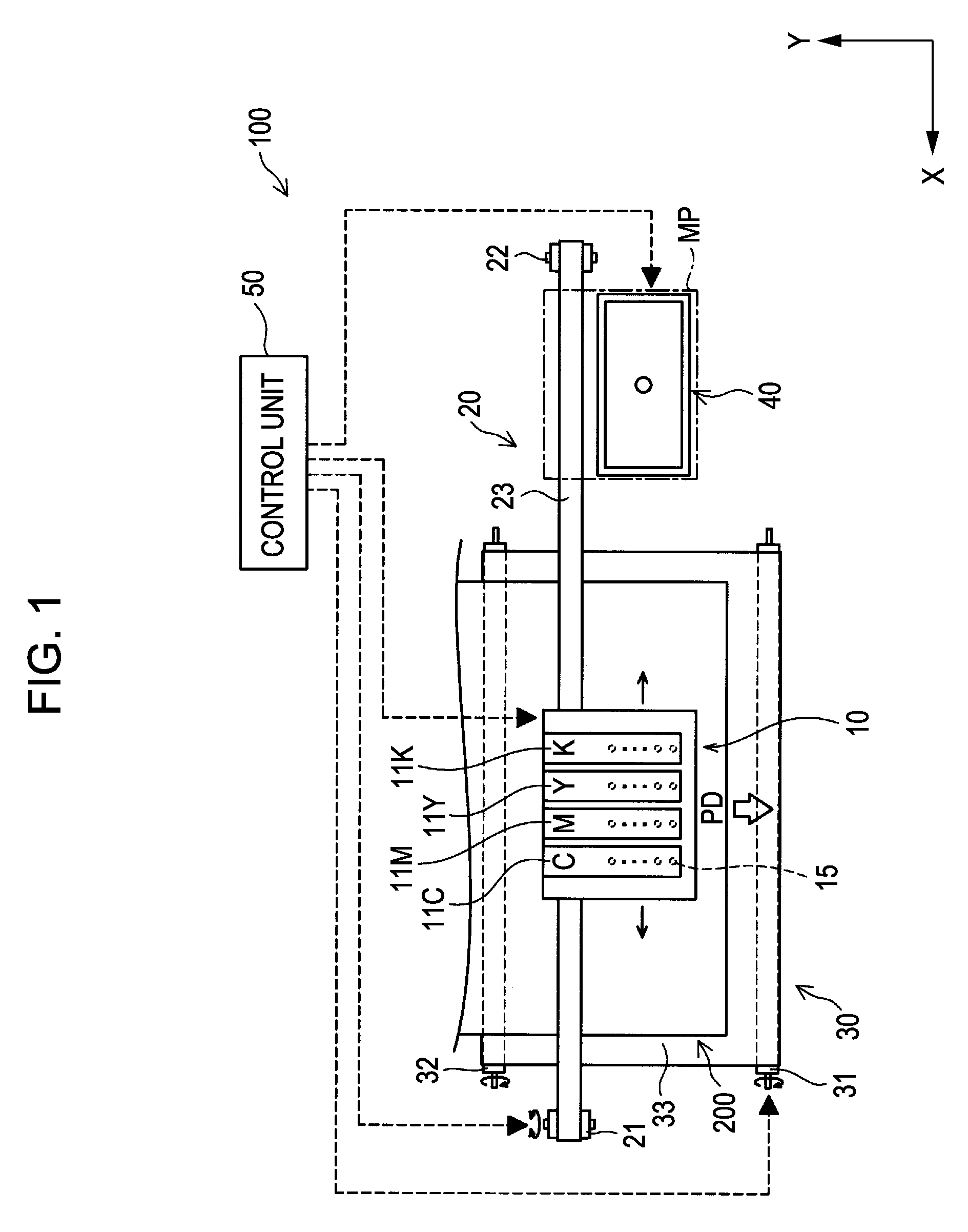
[0044]FIG. 1 is a schematic view that shows the configuration of an ink jet printer according to an embodiment of the invention. The ink jet printer 100 is an ink jet printing apparatus that forms an image by discharging ink droplets of a plurality of colors onto a sheet face in accordance with print data transmitted externally. The ink jet printer 100 includes a print head unit 10, a head driving unit 20, a paper transport unit 30, a cap unit 40, and a control unit 50.

[0045]The print head unit 10 has detachably mounted ink cartridges 11C, 11M, 11Y, and 11K of four colors consisting of cyan, yellow, magenta and black. When the ink jet printer 100 performs printing, the print head unit 10 repeats reciprocal movement in a vertical direction (arrow X direction in the drawing) with respect to a transport direction PD of a print sheet 200 while discharging ink droplets of respective colors toward the paper face. Note that the number of colors of ink cartridges mounted on the print head u...


PUM


Abstract

A fluid ejecting apparatus that ejects fluid includes: a pressure chamber that is filled with the fluid; a pressure generating element that deforms a wall face of the pressure chamber to change a volume of the pressure chamber; a nozzle that is in fluid communication with the pressure chamber and that is used for ejecting the fluid; and a control unit that generates a drive pulse for controlling the pressure generating element. The control unit is able to generate a maintenance drive pulse for ejecting a bubble together with the fluid from the pressure chamber. The maintenance drive pulse includes a first pulse portion that drives the pressure generating element to cause the pressure chamber to expand into an expanded state and a second pulse portion that causes the pressure chamber to contract from the expanded state. The width of the second pulse portion is equal to or smaller than half the Helmholtz resonance period of the fluid with which the pressure chamber is filled.

Description

[0001]This application claims priority to Japanese Patent Application No. 2008-143690, filed May 30, 2008 and to Japanese Patent Application No. 2009-036416, filed Feb. 19, 2009. The entire disclosures of the aforementioned applications are incorporated herein by reference.BACKGROUND[0002]1. Technical Field[0003]The present invention relates to a fluid ejecting apparatus that ejects fluid from a nozzle.[0004]2. Related Art[0005]An ink jet printer performs printing by discharging (ejecting) ink droplets from nozzles toward a sheet face. In the ink jet printer, because of thickened ink adhered to nozzle openings due to natural evaporation or absorption of pressure change in ink chambers by bubbles trapped in the ink chambers that are filled with ink, poor discharge of ink droplets may occur.[0006]In order to keep favorable discharge of ink droplets, various techniques for a maintenance process have been suggested, which are, for example, described in JP-A-2007-136989, JP-A-59-131464. ...

Claims


Application Information

Patent Timeline
Patent Type & Authority Applications(United States)
IPC IPC(8): B41J29/38
CPCB41J2/0451B41J2/04551B41J2/16526B41J2/04588B41J2/04596B41J2/04581
Inventor HOSONO, SATORUKAWAKAMI, SAYURI
Owner SEIKO EPSON CORP
Why Eureka
Try Eureka