Illuminating unit and projection type image display apparatus using the same

a technology of projection type and display apparatus, applied in fixed installation, lighting and heating apparatus, instruments, etc., can solve the problem of not having a suggestion to satisfy this requirement, and achieve the effect of discharging the heat generated by the light emitting devi

Inactive Publication Date: 2008-02-19
SAMSUNG ELECTRONICS CO LTD
View PDF17 Cites 52 Cited by
  • Summary
  • Abstract
  • Description
  • Claims
  • Application Information

AI Technical Summary

Benefits of technology

[0008]The present invention provides an illuminating unit for holding a plurality of optical modules including small light emitting devices such as LEDs, collimators for reflecting the light beams output from the light emitting devices in a predetermined direction, and a fixing member having a structure capable of effectively, discharging the heat generated by the light emitting devices.

Problems solved by technology

Unfortunately, there has been no suggestion for satisfying this requirement.

Method used


Image

  • Illuminating unit and projection type image display apparatus using the same
  • Illuminating unit and projection type image display apparatus using the same
  • Illuminating unit and projection type image display apparatus using the same

Examples


first embodiment

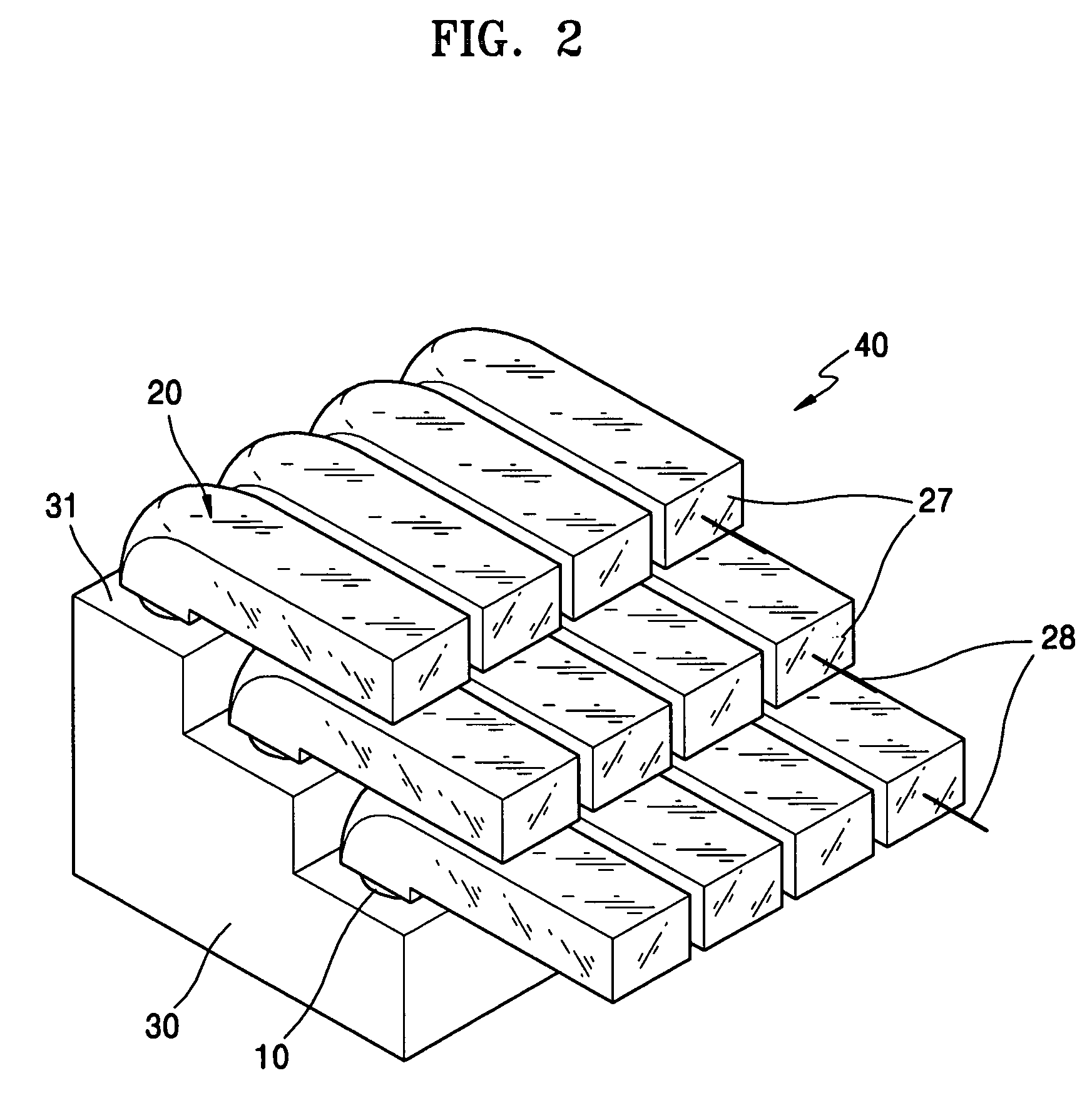
[0034]FIG. 2 is a perspective view of an example of an illuminating unit according to the present invention.

[0035]The illuminating unit 40 has a fixing member 30, a plurality of light emitting diodes (LEDs) 10, and collimators 20 coupled to the LEDs 10.

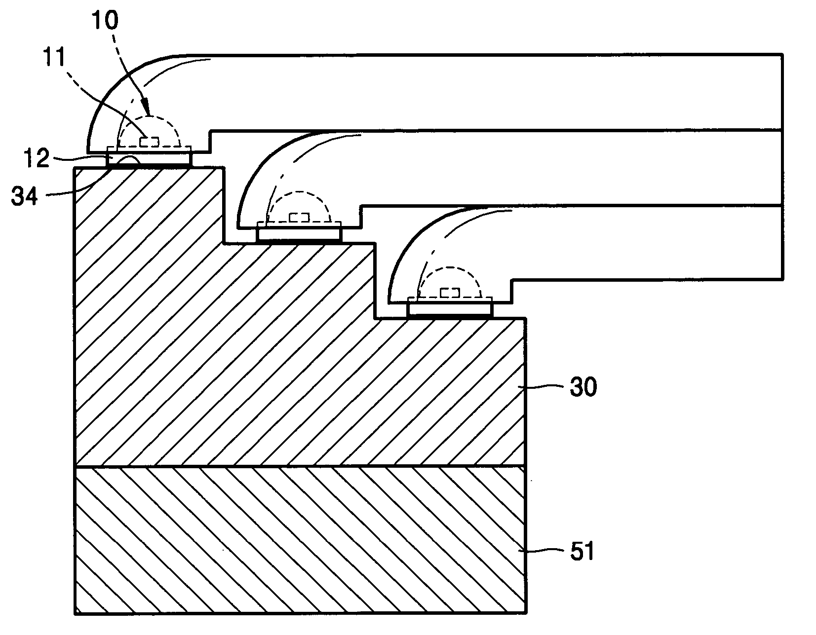
[0036]The fixing member 30 has a 3-step structure. The top surface 31 of each step is sufficiently large to mount the collimator 20. The LEDs 10 are installed on each top surface 31, and the collimator 20 covers the LED 10, so that the light beam output from the LED is collimated by the collimator 20. Further, a plurality of collimators 20 are arranged to guide the light beams to the same direction. That is, the collimators 20 are arranged in such a way that the normal vectors of the light output surfaces 27 of the collimators 20 are directed to the same direction.

[0037]The LEDs 10 and the collimators 20 will now be described in more detail with reference to FIGS. 3 and 4.

[0038]The LED 10 has an LED chip 11 mounted on a substrate 12. ...

second embodiment

[0046]FIG. 5 is a perspective view of an illuminating unit according to the present invention, and FIG. 6 is a cross-sectional view along a line VI-VI of FIG. 5.

[0047]In the second embodiment, the fixing member 30 and the LEDs 10 have the same structure as in the first embodiment. Also, first through third collimators 35a, 35b, and 35c according to the second embodiment have the same structure as in the first embodiment, except that the lengths of the light guide sections 36a, 36b, and 36c are different.

[0048]Referring to FIGS. 5 and 6, the illuminating unit 50 includes a fixing member having a 3 step structure, a plurality of LEDs mounted on the top surfaces of each step, and first through third collimators 35a, 35b, and 35c.

[0049]The LEDs 10 are mounted on the top surfaces 31 of the steps. The first through third collimators 35a, 35b, and 35c are installed to cover the LEDs 10 so that the light beams from LEDs 10 can be collected. Also, the first through third collimators 35a, 35...

third embodiment

[0057]FIG. 9 is a perspective view of an illuminating unit 80 having first and second fixing members 70a and 70b according to the present invention.

[0058]The illuminating unit 80 according to the third embodiment of the present invention includes LEDs 10, upper and lower collimators 75a and 75b, and first and second fixing members 70a and 70b having a 2-step structure. The first stepped top surface 71a of the first fixing member 70a faces the second stepped top surface 71b of the second fixing member 70b.

[0059]The LEDs 10 used in this embodiment have the same configuration as those used in the first embodiment, and the upper and lower collimators 75a and 75b also have the same configuration as those used in the first embodiment, except for the lengths of the light guide sections. In comparison with the first and second embodiments, the first and second fixing members 70a and 70b according to the third embodiment have a 2-step structure.

[0060]The light guide sections of the upper an...


PUM

PropertyMeasurementUnit
refractive indexaaaaaaaaaa
wavelengthsaaaaaaaaaa
lengthaaaaaaaaaa

Abstract

An illuminating unit having a plurality of light emitting devices and collimators and a projection type image display apparatus using the same are provided. The illuminating unit includes: a plurality of light emitting devices which output light beams of predetermined wavelengths; a plurality of collimators, each having a parabolic reflection surface for reflecting the light beam in a predetermined direction, a mounting section for locating the light emitting device at the focal point of the parabolic reflection surface, a light output surface opposite to the parabolic reflection surface, and a light guide section for guiding the light beam reflected from the parabolic reflection surface to the light output surface; and one or more fixing members having two or more steps for mounting the light emitting devices and the collimators on their top surface. A plurality of light emitting devices and collimators are efficiently arranged in a small space. Therefore, thermal concentration can be reduced and heat can be effectively discharged.

Description

CROSS-REFERENCE TO RELATED PATENT APPLICATIONS[0001]This application claims priority from Korean Patent Application No. 10-2005-0019066, filed on Mar. 8, 2005, in the Korean Intellectual Property Office, the disclosure of which is incorporated herein in its entirety by reference.BACKGROUND OF THE INVENTION[0002]1. Field of the Invention[0003]The present invention relates to an illuminating unit and a projection type image display apparatus using the same and, more particularly, to an illuminating unit having an improved fixing member for mounting light sources and collimators and a projection type image display apparatus using the same.[0004]2. Description of the Related Art[0005]Typically, an illuminating unit includes a light source for outputting a light beam, an illuminating optical module such as a collimator for transferring the light beam output from the light source, and a fixing member for holding the light source and the illuminating optical module. The illuminating unit i...

Claims


Application Information

Patent Timeline
Patent Type & Authority Patents(United States)
IPC IPC(8): F21V5/04F21K99/00
CPCG02B6/0018G02B6/0021G02B6/10G02B27/0905G02B27/0983G02B27/0994G03B21/2033G03B21/2066G03B21/208F21K9/00F21K9/52F21Y2101/02Y10S362/80F21K9/61F21Y2115/10F21K9/68B21F37/00B21F1/00
Inventor LEE, KYE-HOONLEE, WON-YONGLEE, YOUNG-CHOL
Owner SAMSUNG ELECTRONICS CO LTD
Why Eureka
Try Eureka