

Print control system and computer program stored in a computer readable medium
- Summary
- Abstract
- Description
- Claims
- Application Information
AI Technical Summary
Benefits of technology
Problems solved by technology
Method used
Image

Examples
Embodiment Construction
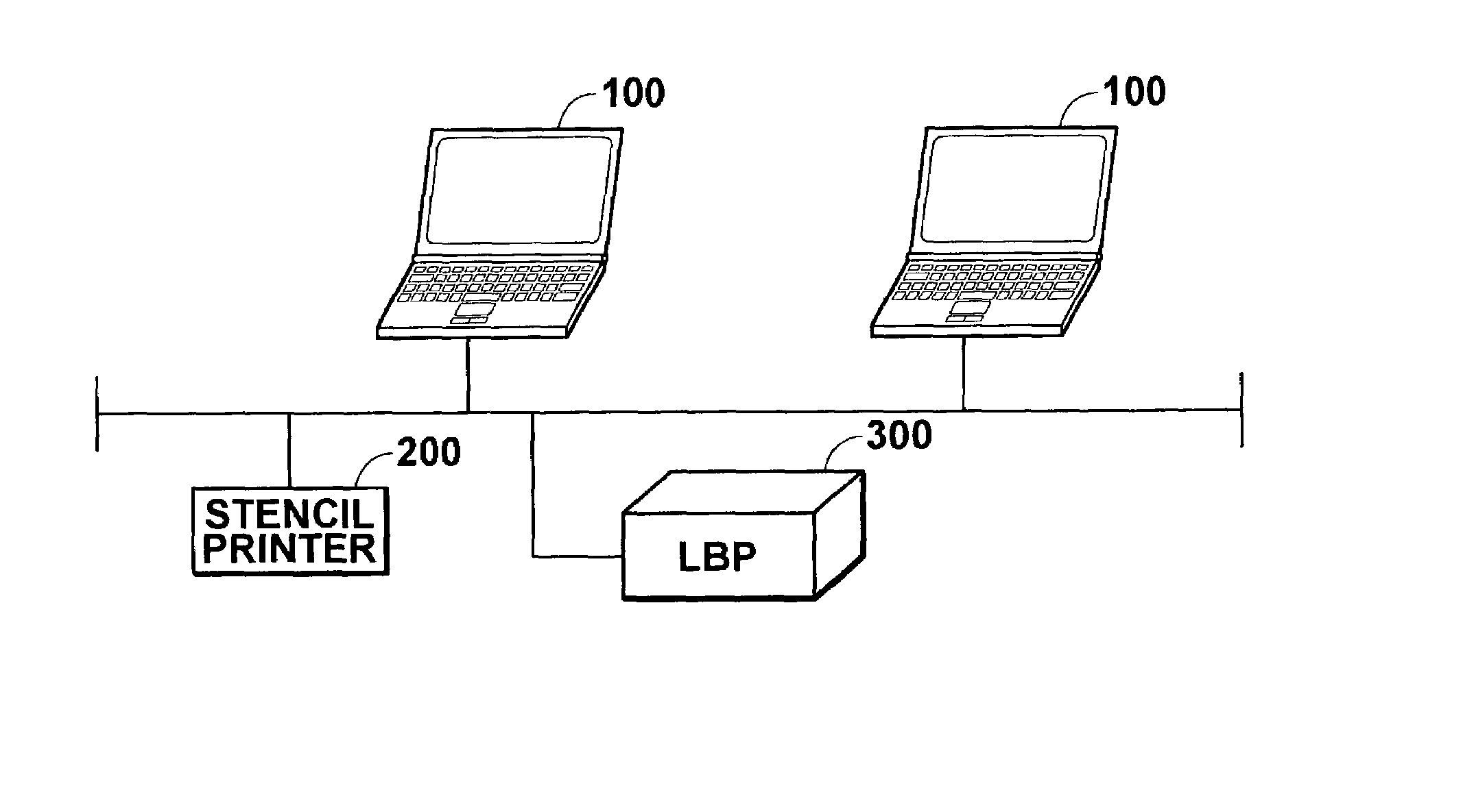
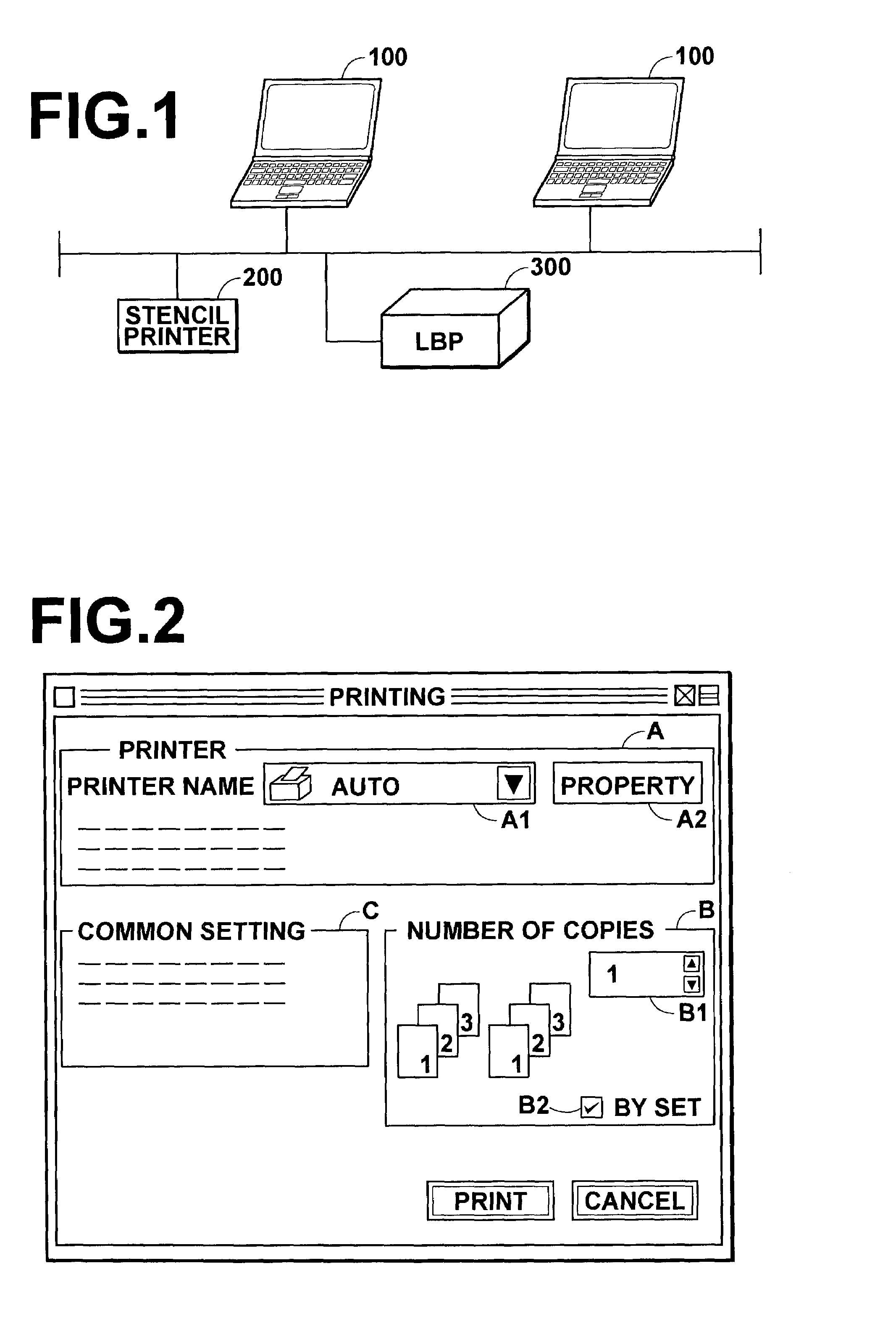
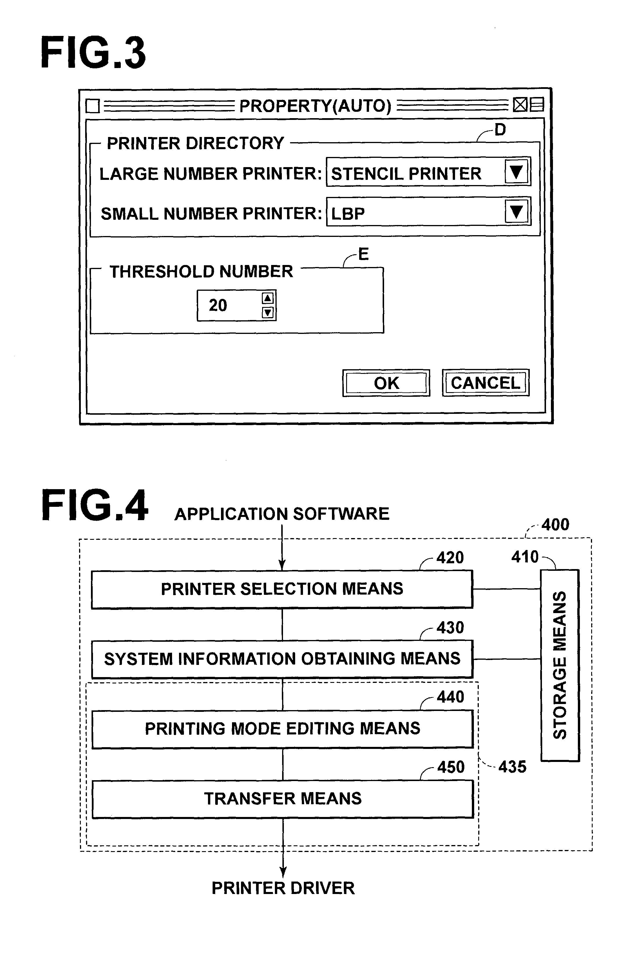
[0042]In FIG. 1, a print system in accordance with an embodiment of the present invention comprises computers 100 which output a printing job, a stencil printer 200, and LBP (a laser beam printer) 300 which are connected by way of a network. An application software which creates printing data and sets printing condition, printer drivers for the stencil printer 200 and the LBP 300 and a utility for automatically selecting one of the stencil printer 200 and the LBP300 (a computer program in accordance with an embodiment of the present invention) are installed in the computers 100.
[0043]FIG. 2 is a view showing in brief a printing condition setting screen for setting the printing condition for printing data which has been created by the computer 100. As shown in FIG. 2, the printing condition setting screen provided by the application software comprises a printer setting dialog box A for setting a printer to which the printing data is to be output, a copy number setting dialog box B fo...
PUM
 Abstract
Description
Claims
Application Information