Method for producing an end lug of a spring member formed of a strand of wire, and apparatus for manufacturing same

a technology of end lugs and spring members, which is applied in the field of forming end lugs on spring members, can solve the problems of affecting the production efficiency of the difficulty of forming the second (rear) german lug, and the inability of the gripping tongs to grip in such a way that a vertical mill could be used, so as to achieve high precision the production of rear lugs and increase the operational safety of the production process

Inactive Publication Date: 2008-02-26
WAFIOS AKTIENGES
View PDF11 Cites 6 Cited by
  • Summary
  • Abstract
  • Description
  • Claims
  • Application Information

AI Technical Summary

Benefits of technology

[0008]Thus, in the solution according to the invention, a pair of gripping tongs is used in which one of the two clamping jaws is formed as a shaping jaw, while the other serves as a bending pin for bending the lug into its shape. This makes it possible, in the method according to the invention, even when the wire segment at the end of the spring is too short and when a German lug is to be formed there, to be able nonetheless to grip said wire segment with the gripping tongs formed in accordance with the invention. This is because during the subsequent bending of the rear wire segment around the shaping jaw of the gripping tongs, separate, additional space is required to allow the gripping tongs to grip outside the bent lug shape on the side toward which bending takes place is no longer necessary.
[0009]The method according to the invention now makes this possible, so that both stem lugs and normal German lugs, as well as other lugs, can be manufactured using one set of standard tools without encountering any problems whatsoever. A separate, additional processing station in the form of a lug plate is no longer necessary on the machine; In addition, the additional gripping tongs previously required for conveyance to the lug plate can also be fully eliminated.
[0010]The method according to the invention allows for a highly precise production of the rear lugs manufactured therewith, even in the case of German lugs, thereby increasing the operational safety of the production process for such tension springs. Moreover, the method of the invention allows for the production of lugs in a shorter period of time than can be achieved using conventional methods, due to the intermediate steps required in said methods. Thus, the production method according to the invention also proves, in general, to be especially cost-effective.
[0015]An especially advantageous embodiment of the spring production method of the invention is achieved in that, prior to shaping of the rear lug, the spring element, together with the front lug already molded to it and the rear wire segment, are moved, by means of the gripping tongs, out of the spring coiling space of the spring production machine. As a result, the next spring element with a front lug can be manufactured while the machine is shaping the rear lug, thereby substantially increasing the operating efficiency of the machine.
[0018]The apparatus according to the invention is suitable for performing the method according to the invention, and features a significantly simplified structure in comparison to previously known devices, because neither a lug plate nor a second pair of gripping tongs are necessary, for which reason it can also be manufactured more cost effectively than previously known apparatuses for the same purpose. Furthermore, the measures employed in accordance with the invention, especially the forming of one of the clamping jaws of the gripping tongs as a shaping jaw (in the sense of a bending pin), can be executed without significant cost.
[0021]In the apparatus according to the invention, it is also advantageous if the movement devices for the shaping pin also comprise a vertically moveable supporting table and a device for moving the shaping pin perpendicular to the longitudinal direction of the supplied strand of wire. In this case, the shaping pin also sits on a vertical mill mounted on the supporting table, by means of which it can also be moved in a circular motion, which is particularly preferable. Thus, all relative movements between the shaping jaw and the shaping pin required for the formation of the rear lug are easily achieved with simple, easily controllable means.

Problems solved by technology

During production of the lugs, the shaping of the second, i.e., rear lug (at the end of the spring element) is especially problematic, particularly during the production of German lugs.
The production of a second (rear) German lug, however, is significantly more complex and requires additional equipment.
However, only a short piece of wire would be necessary to form the second, that is, rear lug, which, however, a pair of gripping tongs would no longer be able to grip in such a way that a vertical mill could be used.
However, a lug plate and a separate pair of gripping tongs are relatively costly additional devices and, furthermore, adjustment of a lug plate is rather complicated.

Method used


Image

  • Method for producing an end lug of a spring member formed of a strand of wire, and apparatus for manufacturing same
  • Method for producing an end lug of a spring member formed of a strand of wire, and apparatus for manufacturing same
  • Method for producing an end lug of a spring member formed of a strand of wire, and apparatus for manufacturing same

Examples


Embodiment Construction

[0025]In the following description relating to the depictions of the individual figures, identical parts are consistently identified with the same reference symbols.

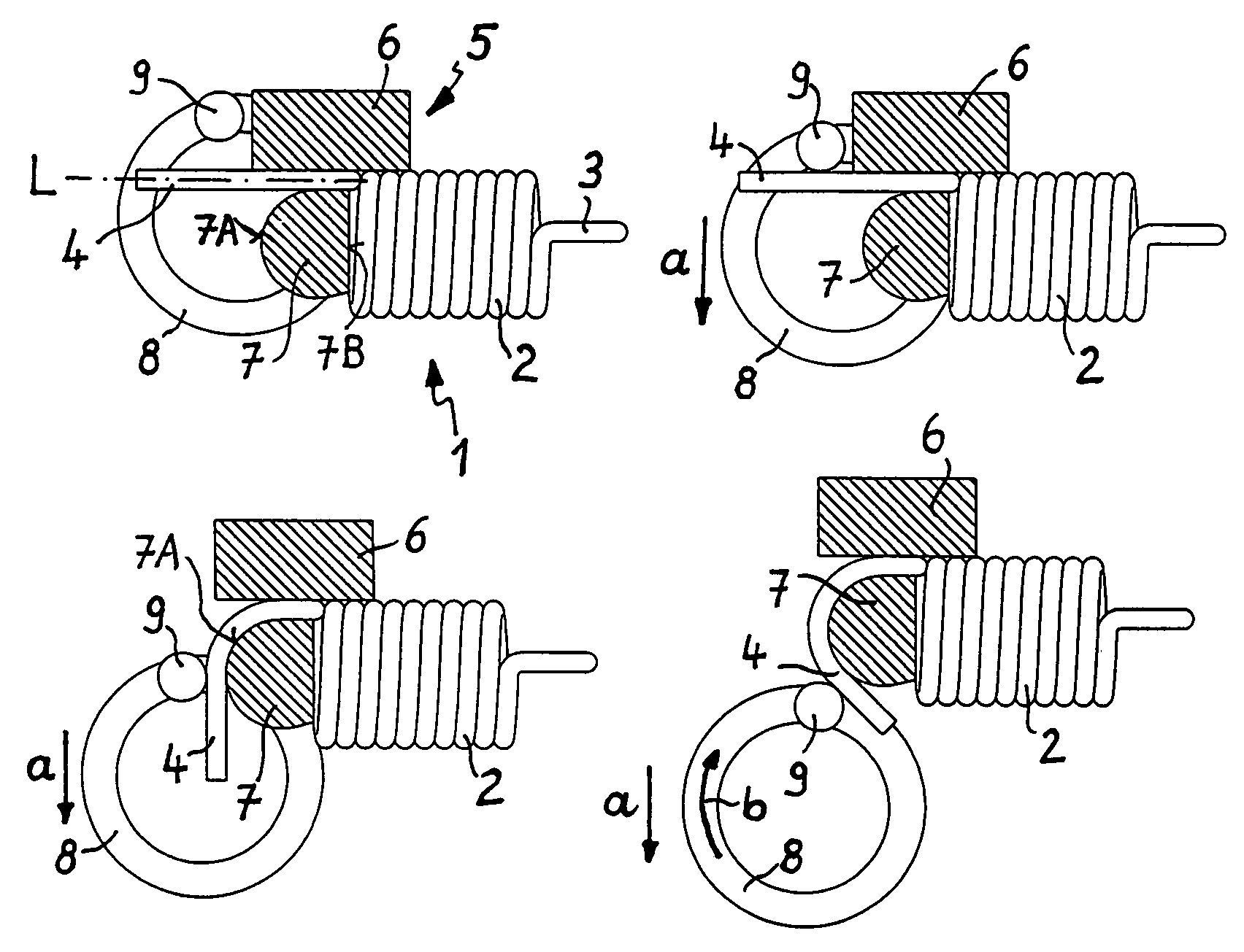
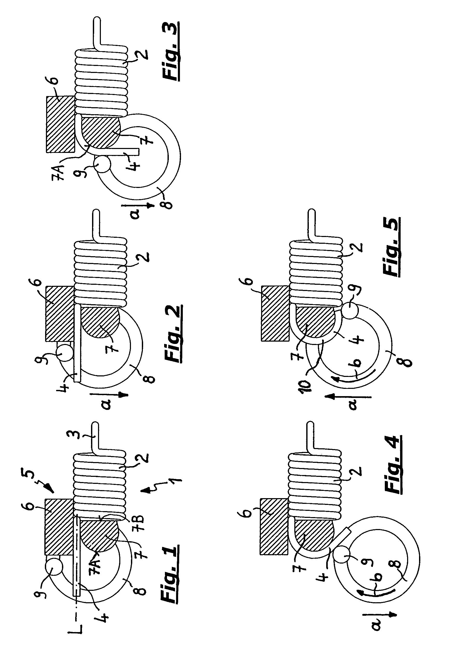
[0026]In FIGS. 1 to 5, the completion of the individual steps for forming a “German lug” is initially shown in an enlarged depiction.

[0027]The figures initially show a spring 1, which consists of a spring element 2 previously formed on a spring coiling machine (not shown), the front end of which is provided with a front lug 3, which is also already formed. At its rear (located to the left in the figures) end, which faces the wire feed, a rear wire segment 4 protrudes from the spring element 2, said wire segment already having been severed from the supplied strand of wire in a preceding step.

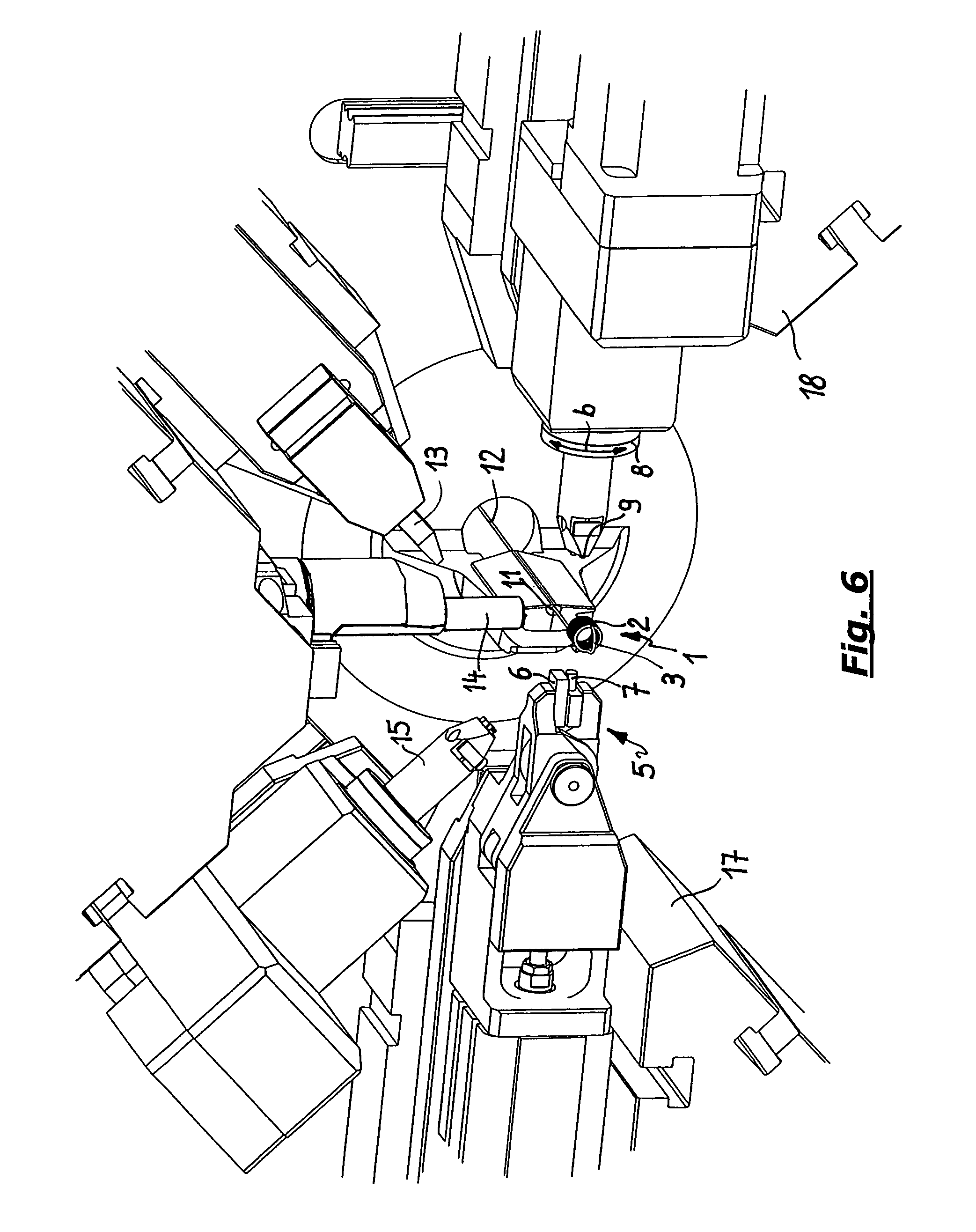
[0028]As the figures show, the spring 1 is gripped at the rear wire segment 4 by a pair of gripping tongs 5 directly behind the spring element 2, said gripping tongs having two (shown in a schematic sectional view in the figures) clam...


PUM

PropertyMeasurementUnit
distanceaaaaaaaaaa
shapeaaaaaaaaaa
timeaaaaaaaaaa

Abstract

A method and apparatus for producing an end lug of a spring member formed of a strand of wire, the strand of wire is initially gripped by two clamping jaws or a pair of tongs, held between said clamping jaws and, subsequently, at a predetermined distance behind the gripping tongs, while forming a rear wire segment protruding behind the spring element, is severed. In this regard, a shaping jaw conforming to the shape of the lug is employed as the one clamping jaw of the gripping tongs, around which the wire segment is bent by means of a shaping pin that can be inserted directly behind the other clamping jaw perpendicular to the longitudinal center line of the wire segment over the latter to form the lug. The relative movements between the shaping pin and the shaping jaw required for this purpose are generated by means of program-controlled movements of the gripping tongs and / or shaping pin.

Description

FIELD OF THE INVENTION[0001]The invention relates to the forming of end lugs on spring members formed from a strand of wire on a spring production machine.BACKGROUND OF THE INVENTION[0002]If springs in the form of tension springs must be used, it is necessary to provide them with lugs at both ends during production. Various lug forms are known, especially stem lugs (in which the lug sits on a stem progressing away from the spring element at a specific distance) as well as so-called “normal German lugs,” in which the lug sits directly, and without formation of an intermediate stem, on the applicable end of the spring element. During production of the lugs, the shaping of the second, i.e., rear lug (at the end of the spring element) is especially problematic, particularly during the production of German lugs.[0003]The production of a first (front) lug on the uncut wire directly in the spring production machine, such as a spring coiling machine, no longer presents a problem when a vert...

Claims


Application Information

Patent Timeline
Patent Type & Authority Patents(United States)
IPC IPC(8): B21F35/02B21F11/00B21F3/00B21F3/02B21F35/00
CPCB21F3/02B21F35/02
Inventor SPECK, NORBERT
Owner WAFIOS AKTIENGES
Why Eureka
Try Eureka