Delivery device for leaflet valve

a delivery device and leaflet valve technology, applied in the field of leaflet valve delivery devices, can solve the problems of valve leaflets, heart failure and death, thickening, and subsequent immobility or reduced mobility,

Inactive Publication Date: 2008-02-26
HLT INC
View PDF66 Cites 224 Cited by
  • Summary
  • Abstract
  • Description
  • Claims
  • Application Information

AI Technical Summary

Benefits of technology

[0014]The present invention includes a method of treating the individual leaflets of a targeted heart valve that includes installing one or more small, one-way valves into the targeted leaflets. These smaller valves can be placed in the leaflet using catheter systems, obviating the need for opening the heart or great vessels, cardiopulmonary bypass, excision of the diseased valve, and a thoracotomy. Additionally, multiple small valve placements might reduce the long-term risks associated with a complete prosthetic valve, because failure of an individual valve will not necessarily lead to cardiac failure. The remaining small valves and remaining healthy native valves might be sufficient to sustain life.

Problems solved by technology

A number of diseases result in a thickening, and subsequent immobility or reduced mobility, of valve leaflets.
The increased resistance to blood flow that a stenosed valve presents eventually leads to heart failure and death.
Naturally, this is a heavily invasive procedure and inflicts great trauma on the body leading usually to great discomfort and considerable recovery time.
One particular drawback with the percutaneous approach disclosed in the Andersen '614 Patent is the difficulty in preventing leakage around the perimeter of the new valve after implantation.
Since it appears that the tissue of the native valve remains within the lumen, there is a strong likelihood that the commissural junctions and fusion points of the valve tissue (as pushed against the lumen wall) will make sealing of the prosthetic valve around the interface between the lumen and the prosthetic valve difficult.
Furthermore, in some patients, the deflection of the leaflets against the lumen walls could potentially obstruct the ostial openings of the lumen.
Although both the traditional open heart valve replacement surgery and the newer percutaneous valve replacement surgery replace a native valve in entirely different ways and both have their drawbacks, the paradigm of these two approaches is identical: Render the native valve useless, either through excision (open heart) or immobilization (percutaneous), and then implant a completely new replacement prosthetic valve to take over.

Method used


Image

  • Delivery device for leaflet valve
  • Delivery device for leaflet valve
  • Delivery device for leaflet valve

Examples


Embodiment Construction

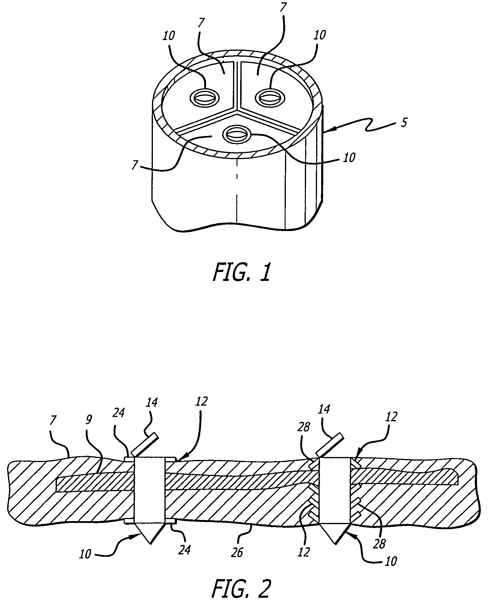
[0054]Referring now to the Figures, and first to FIG. 1, there is shown a native tricuspid valve 5 with a valve implant 10 of the present invention installed in each of the three leaflets 7 of the tricuspid valve 5. The valve implants 10 are shown in an open position to demonstrate that blood is allowed to flow through the valve implants 10, in one direction, even though the native tricuspid valve 5 remains closed. These valve implants 10 would similarly work with a native bicuspid valve, unicuspid valve or quadracuspid valve.

[0055]FIG. 2 demonstrates the positioning of a valve implant 10 in a native leaflet 7. The leaflet 7 is shown as having calcified tissue 9, characteristic of a stenosed valve. Notably, the valve implants 10 have been inserted through the calcified tissue 7. Also notable is that there may be more than one valve implant 10 inserted into a single leaflet 7 if additional flow capacity is desired. Alternatively, though not shown, the valve implant 10 may be installe...


PUM


Abstract

A device and method for improving flow through a native blood vessel valve, such as the aortic valve, are provided. The present invention allows a miniature valve to be implanted into affected leaflets percutaneously, obviating the need for coronary bypass surgery. The method includes the cutting of small holes, on the order of 4 mm, in the leaflets of a targeted valve, thereby allowing blood to flow through the newly formed holes. The holes are used as attachment sites for the miniature valves of the present invention.

Description

CROSS REFERENCE TO RELATED APPLICATIONS[0001]This invention is related to the invention described in the provisional application serial No. 60 / 407,414 filed on Aug. 28, 2002 entitled, MINI-VALVE HEART VALVE REPLACEMENT, and claims priority therefrom.BACKGROUND OF THE INVENTION[0002]Blood vessel valves include flexible tissue leaflets that passively alternate between open and closed positions as the forces of a blood stream act upon them. As blood flows in a first direction, the leaflets are urged apart from each other, and allow the blood to pass. Between pulses, as the blood attempts to flow in a reverse direction, the blood acts upon upstream surfaces of the individual leaflets, causing the leaflets to move inwardly. As the leaflets move inwardly, the edges of the individual leaflets (two, in the case of bicuspid valves, and three in the case of tricuspid valves) abut against each other, effectively blocking the blood flow in the reverse direction.[0003]Valves are also present wit...

Claims


Application Information

Patent Timeline
Patent Type & Authority Patents(United States)
IPC IPC(8): A61B17/34A61B17/32A61FA61F2/24
CPCA61F2/2418A61F2/2463A61F2/2427Y10S623/904A61F2/2466
Inventor WILSON, ROBERT FOSTERWILSON, SCOTT ROBERTPOKORNEY, JAMES L.
Owner HLT INC
Why Eureka
Try Eureka