Lithium ion secondary battery

a secondary battery and lithium ion technology, applied in the direction of non-aqueous electrolyte cells, cell components, sustainable manufacturing/processing, etc., can solve the problems of internal short-circuit, internal short-circuit, ignition of flammable negative electrode active materials, etc., and achieve high safety

Inactive Publication Date: 2008-02-26
GK BRIDGE 1
View PDF10 Cites 196 Cited by
  • Summary
  • Abstract
  • Description
  • Claims
  • Application Information

AI Technical Summary

Benefits of technology

[0017]In view of the above-described findings, an object of the present invention is to produce a wound-type lithium ion secondary battery with high safety by preventing the short-circuit between burrs of a positive electrode current collector and a negative electrode active material part.

Problems solved by technology

Such deformation may trigger an internal short-circuit.
Also, deviation in position of the separator upon the winding of the electrode plates may induce an internal short-circuit.
In short-circuit type (3), since the positive electrode current collector and the negative electrode active material are both conductive, the short-circuit between them causes a spark, resulting in ignition of the flammable negative electrode active material.
However, the production process of such a stacked / integrated type electrode plate assembly is generally complicated, and heightening the capacity is also difficult.

Method used


Image

  • Lithium ion secondary battery
  • Lithium ion secondary battery
  • Lithium ion secondary battery

Examples


embodiment 1

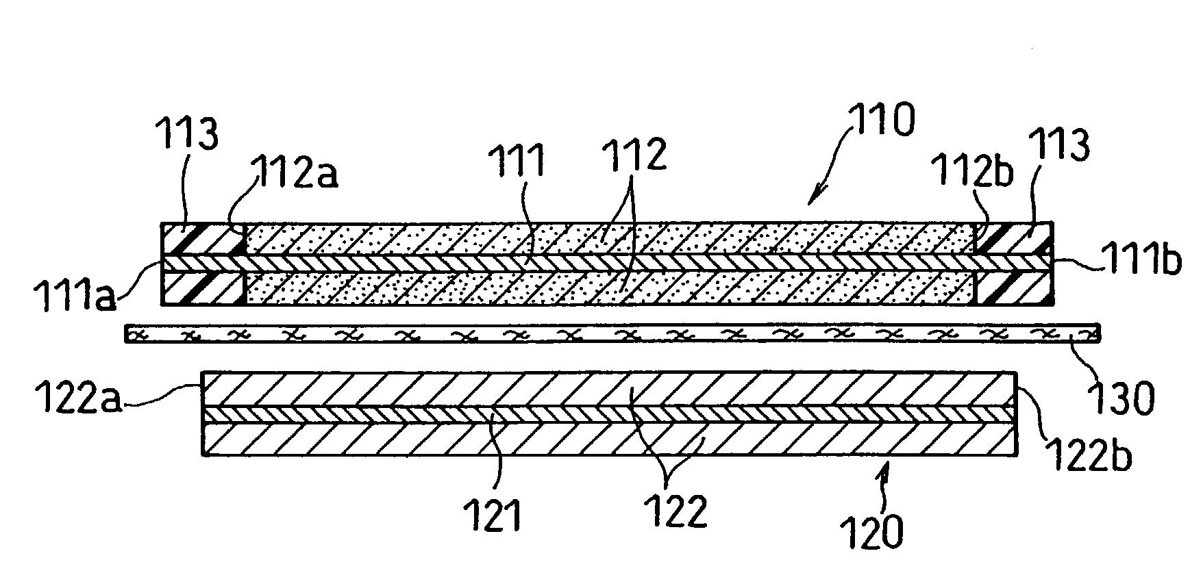
[0045]The lithium ion secondary battery in this embodiment has such a structure that each lengthwise edge of the positive electrode current collector is positioned on an outer side of each lengthwise edge of the negative electrode active material part. Thus, even if burrs occur at the edges of the positive electrode current collector when the positive electrode plate is slit, this structure makes it possible to prevent the short-circuit between the burrs and the negative electrode active material part.

[0046]On each lengthwise end of the positive electrode current collector, a non-active material part which does not absorb or desorb a lithium ion during charge and discharge may be carried. The non-active material part can stabilize the edges of the positive electrode current collector. Further, the thickness of the non-active material part is preferably the same as that of the positive electrode active material part so that there is no difference in height between them and they make ...

embodiment 2

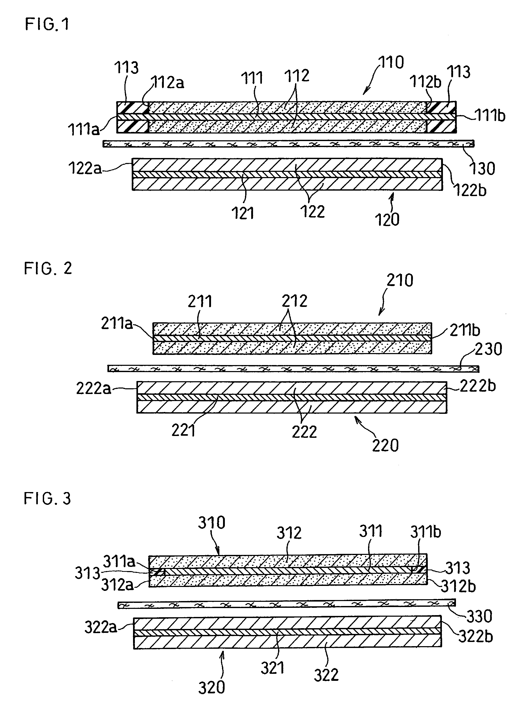
[0055]The lithium ion secondary battery in this embodiment has such a structure that each lengthwise edge of the positive electrode active material part is positioned on an outer side of each lengthwise edge of the positive electrode current collector. In this structure, when the positive electrode active material part is slit near its edges, both the positive electrode current collector and the positive electrode active material part are not slit at the same time, and burrs are therefore unlikely to occur. On the other hand, in the conventional structure as illustrated in FIG. 2, the positive electrode current collector 211 and the positive electrode active material part 212 are slit at the same time, and burrs are therefore likely to occur at the edge 211a or 211b of the positive electrode current collector.

[0056]In this embodiment, it is also preferable that each lengthwise edge of the negative electrode active material part be positioned on an outer side of each lengthwise edge ...

embodiment 3

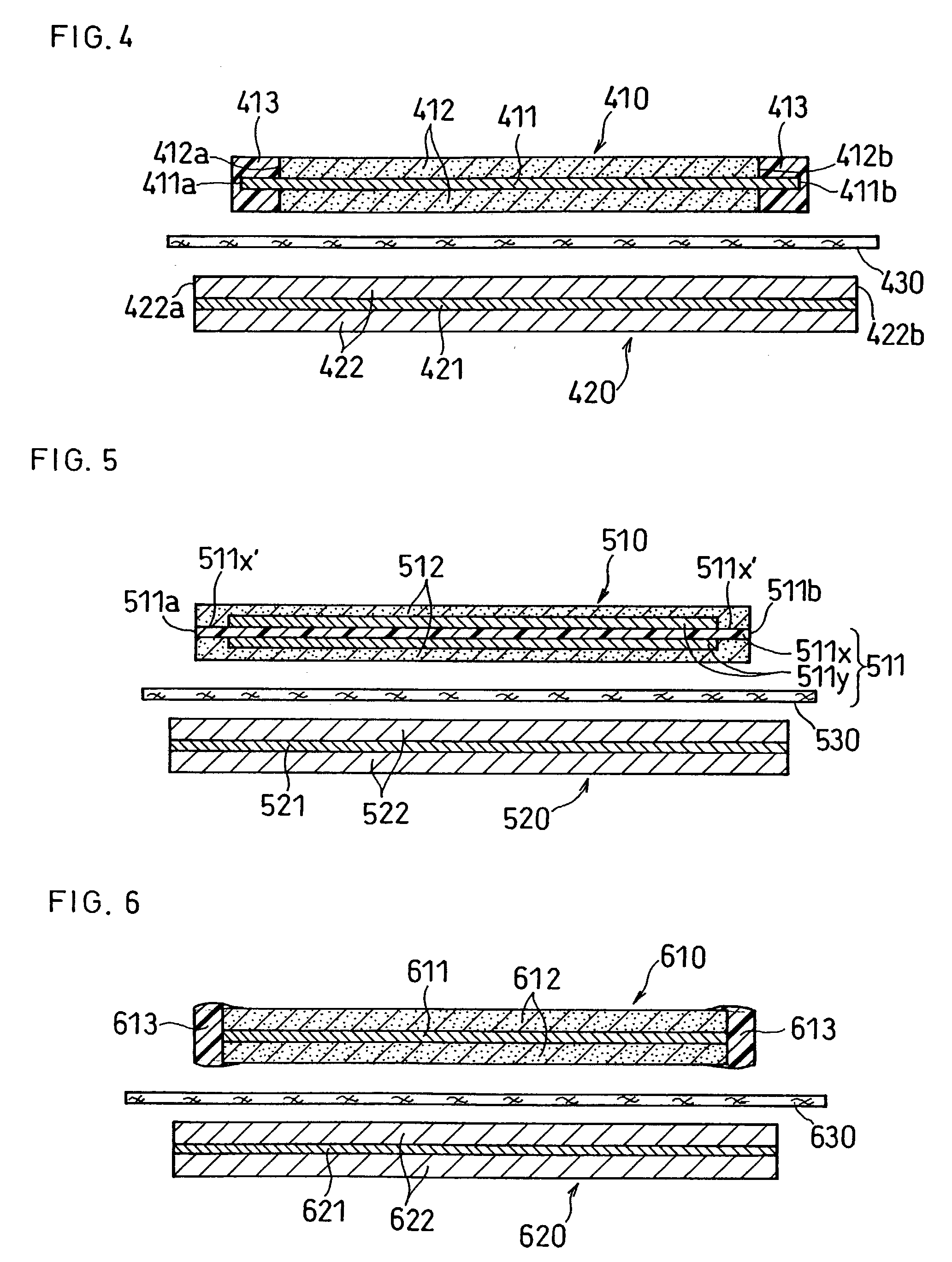
[0066]This embodiment is directed to a lithium ion secondary battery including an electrode plate assembly so configured that each lengthwise edge of the negative electrode active material part is positioned on an outer side of each lengthwise edge of the positive electrode current collector, that each lengthwise edge of the positive electrode current collector is positioned on an outer side of each lengthwise edge of the positive electrode active material part, and that exposed parts of the positive electrode current collector which are not covered with the positive electrode active material part are coated with an insulating material.

[0067]In such an arrangement, the edges of the positive electrode current collector are opposed to the surface of the negative electrode active material part. However, since the exposed parts of the positive electrode current collector which are not covered with the positive electrode active material part are coated with an insulating material, even i...


PUM

PropertyMeasurementUnit
lengthaaaaaaaaaa
thicknessaaaaaaaaaa
thicknessaaaaaaaaaa

Abstract

A lithium ion secondary battery includes: (a) a positive electrode plate comprising an active material part and a current collector carrying the active material part, the active material part comprising a positive electrode active material capable of absorbing or desorbing a lithium ion during charge and discharge; (b) a negative electrode plate comprising an active material part and a current collector carrying the active material part, the active material part comprising a negative electrode active material capable of absorbing or desorbing a lithium ion during charge and discharge; (c) a separator interposed between the positive and negative electrode plates; (d) an electrolyte; and (e) a battery case accommodating the positive and negative electrode plates, the separator, and the electrolyte. The positive and negative electrode plates are wound with the separator interposed therebetween, thereby to form an electrode plate assembly. The electrode plate assembly is so configured that each lengthwise edge of the positive electrode current collector is positioned on an outer side of each lengthwise edge of the negative electrode active material part.

Description

BACKGROUND OF THE INVENTION[0001]With the rapidly growing trend toward cordless and more portable electronic equipment such as audio-visual equipment or personal computers, there is an increasing demand that secondary batteries be smaller and more lightweight with higher energy density as the driving power source. Among such secondary batteries, lithium ion secondary batteries including lithium as an active material particularly have high voltage and high energy density.[0002]Of conventional lithium ion secondary batteries, wound-type batteries are predominant. Wound-type batteries have an electrode plate assembly in which a positive electrode plate and a negative electrode plate are wound with a separator interposed between the electrode plates. The positive electrode plate comprises a positive electrode active material part and a positive electrode current collector carrying the positive electrode active material part, and the negative electrode plate comprises a negative electrod...

Claims


Application Information

Patent Timeline
Patent Type & Authority Patents(United States)
IPC IPC(8): H01M6/18H01M2/18H01M4/00H01M4/58H01M4/64H01M4/13H01M4/66H01M10/0525H01M10/0587H01M10/36H01M50/186H01M50/193H01M50/534H01M50/536
CPCH01M2/08H01M2/1673H01M2/26H01M4/13H01M4/667H01M4/70H01M10/0525H01M10/0587Y02E60/122Y02E60/10H01M50/46Y02P70/50H01M50/186H01M50/536H01M50/193H01M50/534
Inventor KAITO, TSUYOSHITANIGAWA, FUTOSHIARAI, NAOTO
Owner GK BRIDGE 1
Why Eureka
Try Eureka