Scanning device for carrying out a 3D scan of a dental model, sliding panel therefore, and method therefor

a scanning device and dental model technology, applied in the direction of dental prosthetics, tooth crowns, garments, etc., can solve the problems of long processing time, inability to avoid errors, and in practice, and achieve the effect of preventing incorrect operation, advantageously automatically correcting, and high degree of accuracy

Inactive Publication Date: 2008-02-26
SIRONA DENTAL SYSTEMS
View PDF12 Cites 66 Cited by
  • Summary
  • Abstract
  • Description
  • Claims
  • Application Information

AI Technical Summary

Benefits of technology

[0011]In a scanning device thus constructed, the adjustable panel can only assume exactly defined positions. There is thus a finite number of displacement vectors between individual images, which reduces the correlation of the various images to a discrete number of correlation possibilities. In this manner, the number of computations required is substantially reduced. Furthermore, there is no longer any propagation of summed correlation errors. The scanning results are thus more accurate than when scanning according to the prior art.
[0051]An offset of the image segment resulting from a height adjustment of the image detecting unit is advantageously automatically corrected by the evaluation unit. To do this, the evaluation unit implements the direction of displacement which was determined during calibration of the scanning device and which indicates the offset of two images created at different heights which is required in order to move the same image segments of two images scanned in adjacent positions along the direction of displacement so that the two images match each other in the marginal region as far as possible. This also compensates for any possible vertical offset of the images relative to each other as a result of imaging at different heights.

Problems solved by technology

Due to imaging properties and other software-related inaccuracies incurred during the software correlation, errors cannot, in practice, be avoided when joining two correlated images.
In the worst case, these errors can summate when a series of images are joined together.
Furthermore, the technical computation requirements for correlating images with unknown misalignment are very great, which results in a long processing time.

Method used


Image

  • Scanning device for carrying out a 3D scan of a dental model, sliding panel therefore, and method therefor
  • Scanning device for carrying out a 3D scan of a dental model, sliding panel therefore, and method therefor
  • Scanning device for carrying out a 3D scan of a dental model, sliding panel therefore, and method therefor

Examples


Embodiment Construction

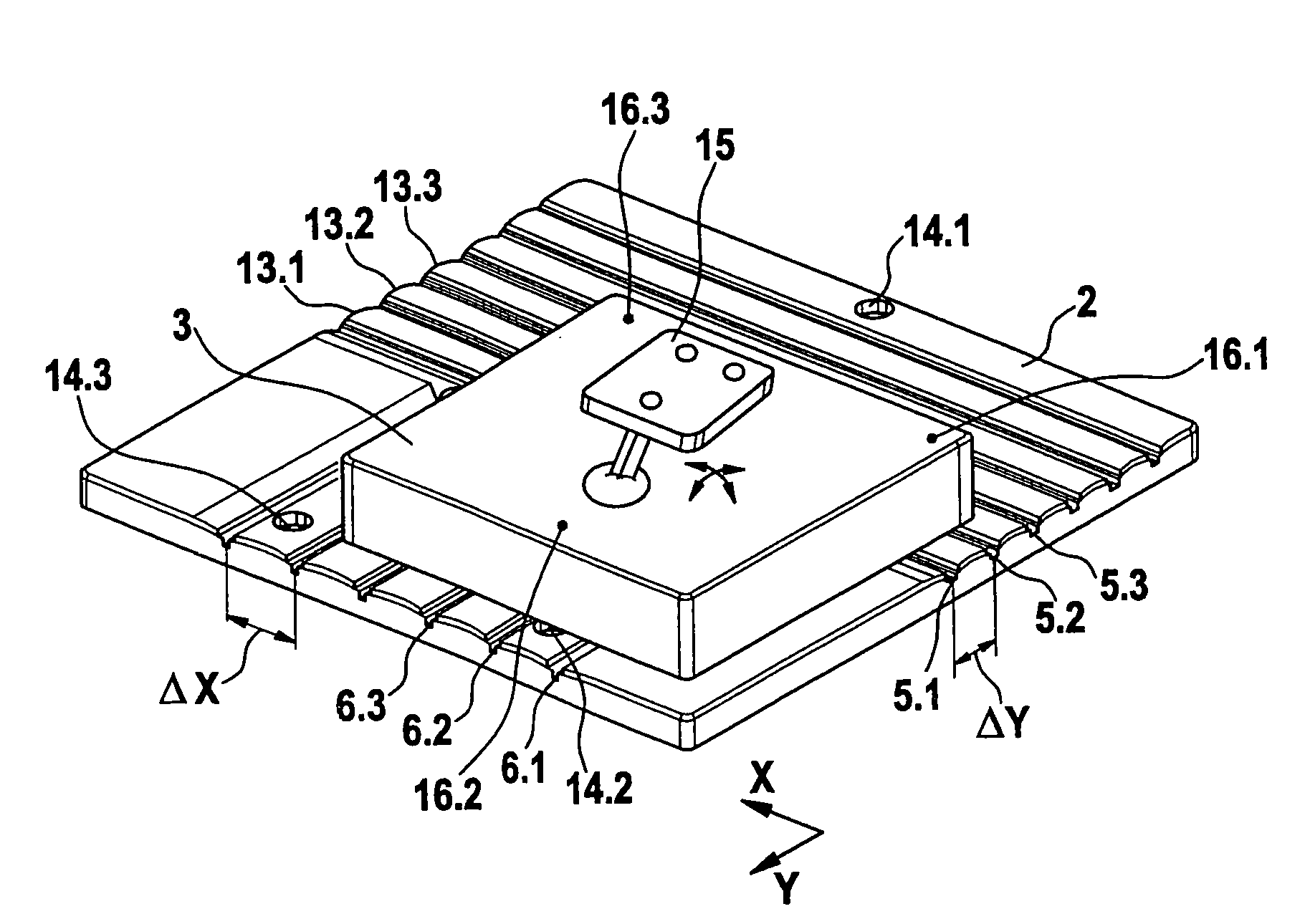
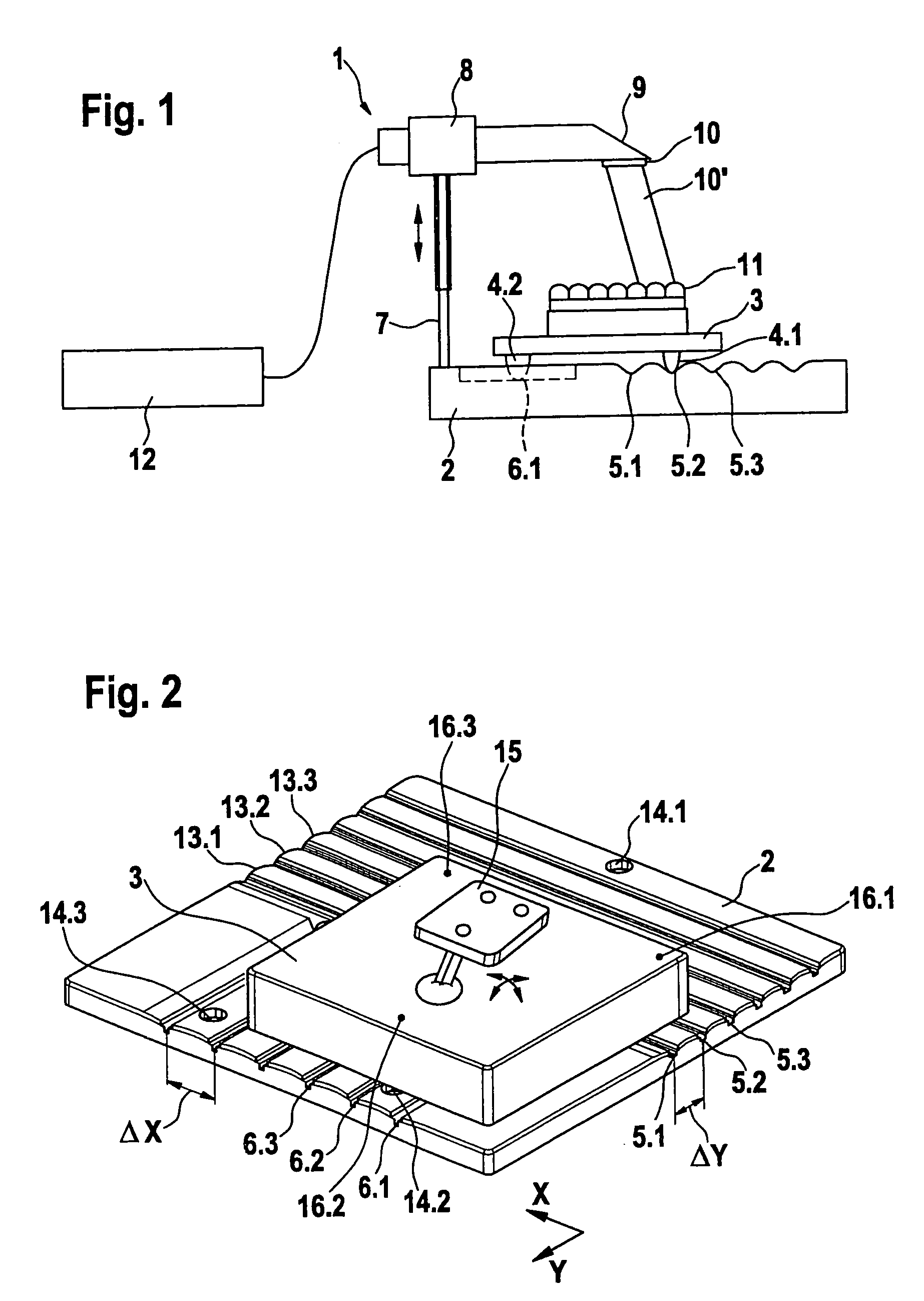
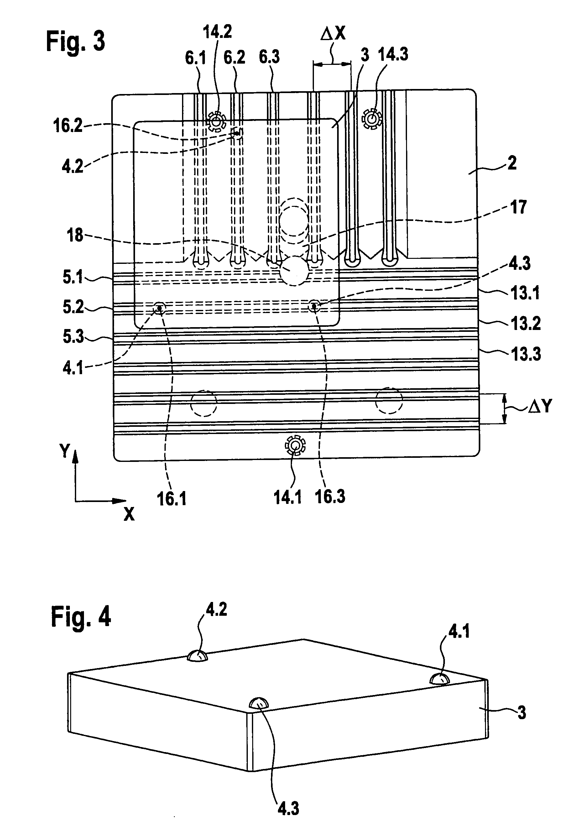
[0064]FIG. 1 is a diagrammatic representation of a scanning device 1 of the invention. The scanning system 1 comprises a locking panel 2, the design of which will be explained in more detail with reference to FIGS. 2 and 3. On the locking panel 2 there is a sliding panel 3 that rests on the locking panel 2 on the projections 4.1, 4.2, 4.3 (not shown). The projections 4.1 and 4.3 slide in the X direction in one of the grooves 5.1, 5.2, 5.3, while the projection 4.2 slides in the Y direction in one of the grooves 6.1, 6.2, 6.3. Engagement of the projections 4.1 and 4.3 in the groove 5.2 and that of the projection 4.2 in the groove 6.1 is illustrated here. The locking panel 2 is provided with a scratch-proof coating having good sliding properties.

[0065]On the locking panel 2 there is additionally provided a column 7, the height of which is adjustable, with a mount 8 for a scanning camera 9 which is in principle an oral scanning camera. The lens of the scanning camera 9 is fitted with a...


PUM

PropertyMeasurementUnit
angleaaaaaaaaaa
angleaaaaaaaaaa
optical pathaaaaaaaaaa

Abstract

A scanning system for carrying out a 3D scan of a tooth model includes an imaging device and a positioning system in the form of a sliding panel which can be positioned and has first locking means. On the locking panel there are provided second locking means which interact with the first locking means such that the sliding panel can assume one of several specified positions relative to the locking panel and locks in the selected position. The sliding panel has means for mounting a dental model and stands on projections disposed on its underside. A 3D scan of a tooth model is provided by creating a first image of the object to be scanned at a precisely defined locked position, moving the sliding panel to at least one further precisely defined locked position and creating another image at each such position, and creating a 3D data set by evaluating the images produced at least two different, precisely defined positions.

Description

BACKGROUND OF THE INVENTION[0001]1. Field of the Invention[0002]The invention relates to a scanning device for carrying out three dimensional scanning of dental models, to a sliding panel therefor, and to a method therefor.[0003]2. The Prior Art[0004]The extraoral scanning of dental impressions or models made from dental impressions with stationary scanning devices is disclosed in the prior art. The object to be scanned is usually larger than the range of image detection of the image detecting unit. It is therefore necessary to create images of the object to be scanned in several segments and to reposition the image detecting unit relatively to the object to be scanned for each image.[0005]A device for determining the shape of a duplicate that contains a clamping device, a sensor contrivance, and a data storage unit, and in which the clamping device and the sensor contrivance are movable relatively to each other, is disclosed in EP 0 913 130 A1.[0006]The individual images are joined...

Claims


Application Information

Patent Timeline
Patent Type & Authority Patents(United States)
IPC IPC(8): H01J3/14A61C5/77
CPCA61C13/0004G01B11/24A61C9/0053Y10T29/49567Y10T29/49568G16H20/40
Inventor EIFF, WOLFGANGFORNOFF, PETER
Owner SIRONA DENTAL SYSTEMS
Why Eureka
Try Eureka