False lock protection in a delay-locked loop (DLL)

a delay-locked loop and false lock protection technology, applied in the direction of electrical equipment, pulse automatic control, etc., can solve the problems of delay clock signal sequence, delay period t might not be set to provide such properly spaced delay clock signal, and additional noise produced by the combined high-low and low-high transition of signals

Active Publication Date: 2008-02-26
ZHANGJIAGANG KANGDE XIN OPTRONICS MATERIAL +1
View PDF13 Cites 91 Cited by
  • Summary
  • Abstract
  • Description
  • Claims
  • Application Information

AI Technical Summary

Problems solved by technology

Initially, the delay period Δt might not be set to provide such properly spaced delayed clock signals spanning one and only one period of the reference clock signal Dref.
Over time, the fixed delay period results in a sequence of delayed clock signals that may or may not span a single period of the reference clock signal.
Using all of the delayed clock signals, however, results in additional noise produced by the signals' combined high-low and low-high transitions.
That is, noise may be an unwanted byproduct of a combinational logic processing a multitude of phases of the reference clock signal.
This noise results from unintentional mixing of signals having a slightly different phase.
Thus, false lock protection circuitry may cause unwanted interfering noise at harmonics of the reference clock frequency.

Method used


Image

  • False lock protection in a delay-locked loop (DLL)
  • False lock protection in a delay-locked loop (DLL)
  • False lock protection in a delay-locked loop (DLL)

Examples


first embodiment

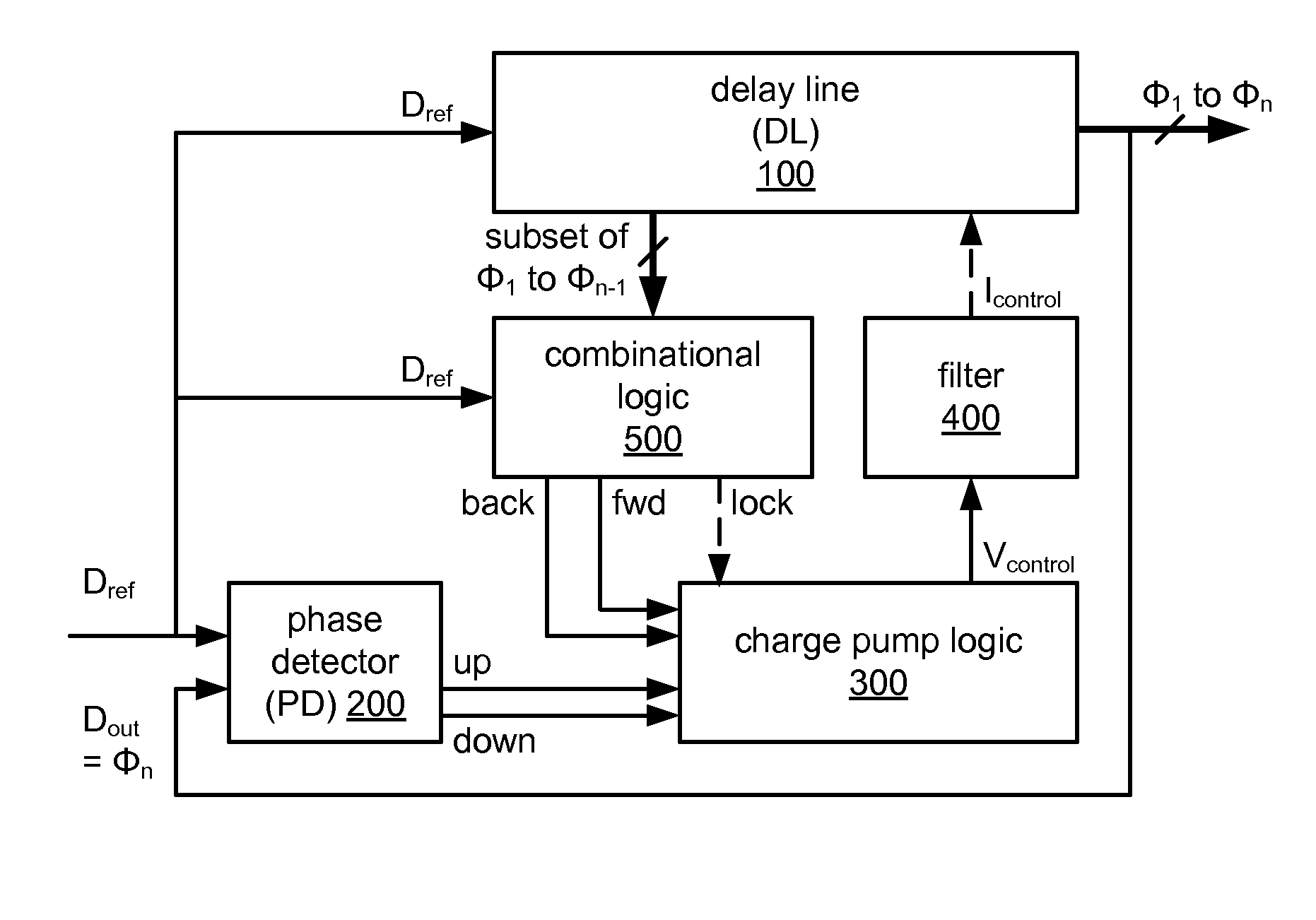
[0071]FIGS. 7A, 7B, 8A and 8B show embodiments of charge pump logic 300 for the DLL of FIG. 4. Charge pump logic 300 may include a single charge pump or may include multiple charge pumps. A first embodiment includes a multiplexer 310 and a single charge pump (CP) 311 as shown in FIG. 7A. Mux 310 accepts down / up indicators as data input signals from PD 200 of FIG. 4. Mux 310 also accepts back / forward indicators as data input signals and the lock indicator as a selection input signal from combinational logic 500 of FIG. 4. Base on the value of the lock indicator, mux 310 passes either the down / up pair or the back / forward pair to charge pump 311. CP 311 then adjusts its output control signal Vcontrol as directed by the indicators provided by mux 310.

second embodiment

[0072]In a second embodiment shown in FIG. 7B, the function of mux 310 of FIG. 7A is implemented with logical gates 320-325 and the function of charge pump 311 of FIG. 7A is implemented with switches 326, 329 and current sources 327, 328. The first switch (S1) 326 is controlled by an output signal from an OR gate 322 having two input ports fed by the output ports of two AND gates 320, 321. The first AND gate 320 accepts the forward indicator as a first input signal and an inverse of the lock indicator as a second input signal. The second AND gate 321 accepts the up indicator as a first input signal and the lock indicator as a second input signal. As implemented, a value of ‘1’ for the up or forward indicators along with the appropriate lock indicator means action (charging the charge pump to increase the control signal to shorten the delay time) and a value of ‘0’ for the up and forward indicators means inaction. The lock indicator is used to pass either the up or forward indicator....

third embodiment

[0074]In a third embodiment shown in FIG. 8A, charge pump logic 300 is implemented with multiple charge pumps 330, 331. A control signal Vcontrol is driven from either charge pump 330, 331. The first charge pump (CP-1) 330 may be active for a first value of the lock indicator while the second charge pump (CP-2) 331 may be active for a complement value of the lock indicator. For example, when combinational logic 500 determines that the DLL is out of a lock state, the lock indicator instructs charge pump logic 300 to activate CP-1330, thereby responding to the back and forward indicators from combinational logic 500 of FIG. 4. When combinational logic 500 determines that the DLL is in a lock state, the lock indicator instructs charge pump logic 300 to activate CP-2331, thereby responding to the up and down indicators from phase detector 200.

[0075]Charge pump logic including multiple charge pumps may advantageously use a first charge pump that has a high current for charging and discha...


PUM


Abstract

A delay-locked loop (DLL) to produce a plurality of delayed clock signals comprising combinational logic for false lock detection is provided. The combinational logic uses only a subset of the plurality of delayed clock signals to provide a forward indicator indicating a delay period (Δt) is longer than a desired delay period. The combinational logic further provides a back indicator indicating the delay period (Δt) is shorter than a desired delay period.

Description

CROSS-REFERENCE TO RELATED APPLICATIONS[0001]Not applicable.BACKGROUND OF THE INVENTION[0002]1. Field of the Invention[0003]The invention relates to delay-locked loops and clock generation, and in particular to false lock protection circuitry incorporated in delay-locked loops.[0004]2. Background of the Invention[0005]A delay-locked loop (DLL) processes a reference clock signal (Dref) to generate a sequence of delayed clock signals. The frequency and period of the reference clock signal Dref are the same as those of each of the generated clock signals however each delayed clock signal is phase shifted by a common delay period (Δt) from the previous delayed clock signal. When operating properly, the DLL provides delayed clock signals with positive edge transitions that span a single period of the reference clock signal Dref. Initially, the delay period Δt might not be set to provide such properly spaced delayed clock signals spanning one and only one period of the reference clock sig...

Claims


Application Information

Patent Timeline
Patent Type & Authority Patents(United States)
IPC IPC(8): H03L7/06
CPCH03L7/0812H03L7/087H03L7/0891H03L7/093H03L7/095H03L7/0816
Inventor SHA, I-TEHZHANG, LIFENGSUN, HAITAOLI, JINGRONG
Owner ZHANGJIAGANG KANGDE XIN OPTRONICS MATERIAL
Why Eureka
Try Eureka