Flexible interconnect cable with grounded coplanar waveguide
What is AI technical title?
AI technical title is built by Patsnap AI team. It summarizes the technical point description of the patent document.
a coplanar waveguide and flexible technology, applied in waveguides, non-printed jumper connections, high-frequency circuit adaptations, etc., can solve the problems of large specialized component packages, cumbersome cable layouts, and preventing the use of differential signaling, and achieve low cost and facilitate high-speed signal transmission.
Inactive Publication Date: 2008-02-26
QUALCOMM INC
View PDF25 Cites 109 Cited by
Summary
Abstract
Description
Claims
Application Information
AI Technical Summary
This helps you quickly interpret patents by identifying the three key elements:
Problems solved by technology
Method used
Benefits of technology
Benefits of technology
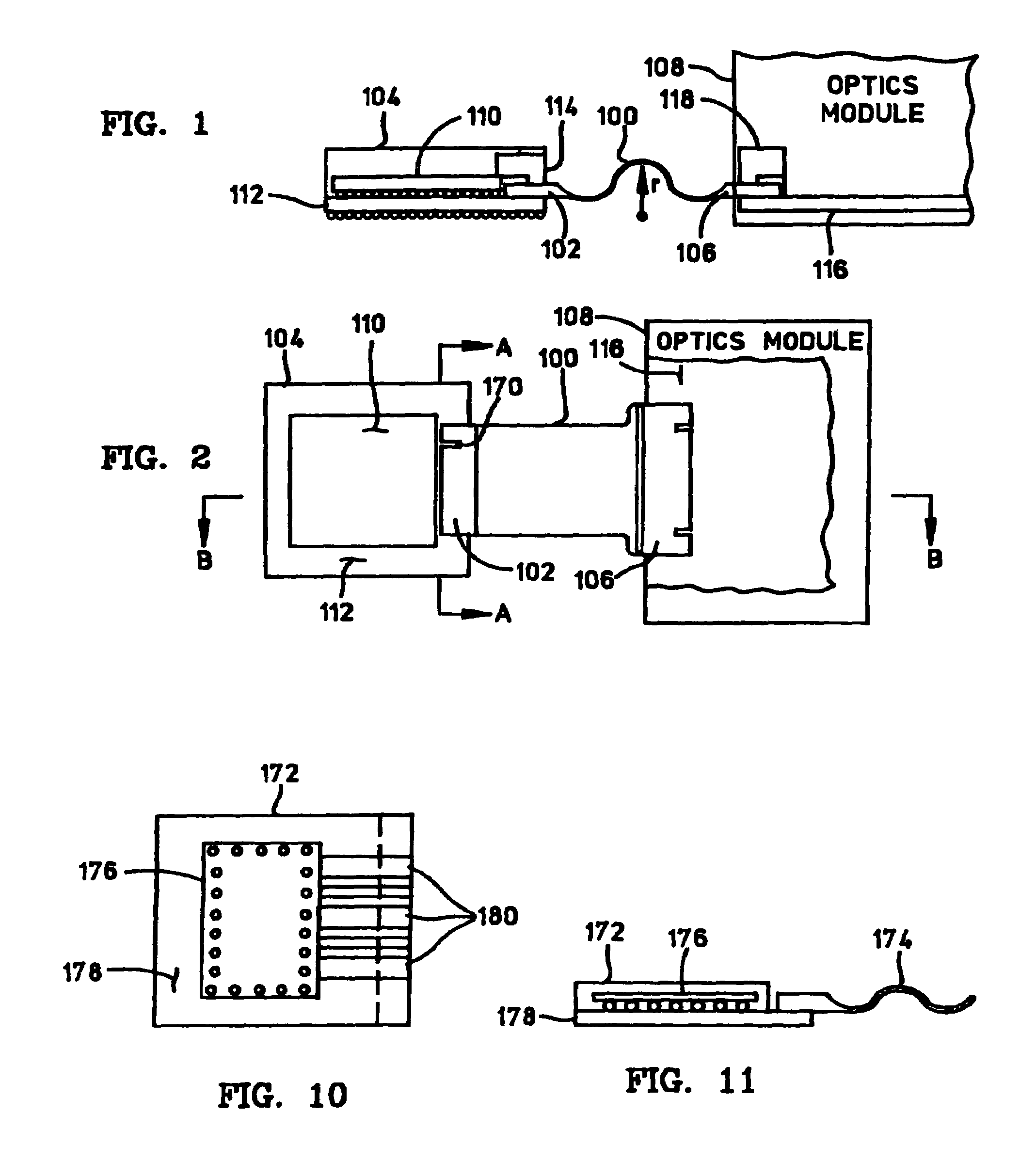
[0007]A flexible electrical interconnect cable according to the present invention facilitates high speed signal transmission between electrical devices, components, modules, circuit boards, and the like. The interconnect cable provides a relatively low cost solution for high speed applications that support data rates of 40 Gbps (and higher). The interconnect cable may also be integrated with a circuit substrate in a manner that eliminates the need to design high speed interconnects within the circuit substrate, e.g., the printed circuit board.
Problems solved by technology
The prior art contains a limited number of interconnect solutions suitable for use at very high speeds (e.g., 40 Gbps and higher).
Such connectors, however, require cumbersome cable layouts, require large specialized component packages, and preclude the use of differential signaling (which provides a number of advantages such as common mode immunity).
The design of the high speed signal interconnects in the circuit substrate can be complex and time consuming, resulting in added manufacturing costs.
Method used
Image
Click on the blue label to locate the original text in one second.
Reading with bidirectional positioning of images and text.
Examples
Embodiment Construction
[0031]The particular implementations shown and described herein are illustrative of the invention and its best mode and are not intended to otherwise limit the scope of the invention in any way. Indeed, for the sake of brevity, conventional RF and microwave transmission line design techniques, flip chip and ball grid array design considerations, substrate interconnect and via design techniques, and manufacturing techniques such as laminating, metal deposition, etching, and the like may not be described in detail herein. In addition, various electronic devices, system components, or modules may be referred to herein as example components to which a flexible interconnect cable may be connected. In practice, the specific type of device, circuit, chip, package, module, circuit board, or component can vary from application to application.
[0032]The present invention provides a flexible electrical interconnect cable having a transmission line structure that is capable of propagating high s...
PUM
Abstract
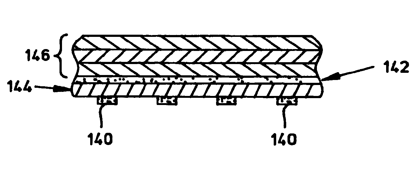
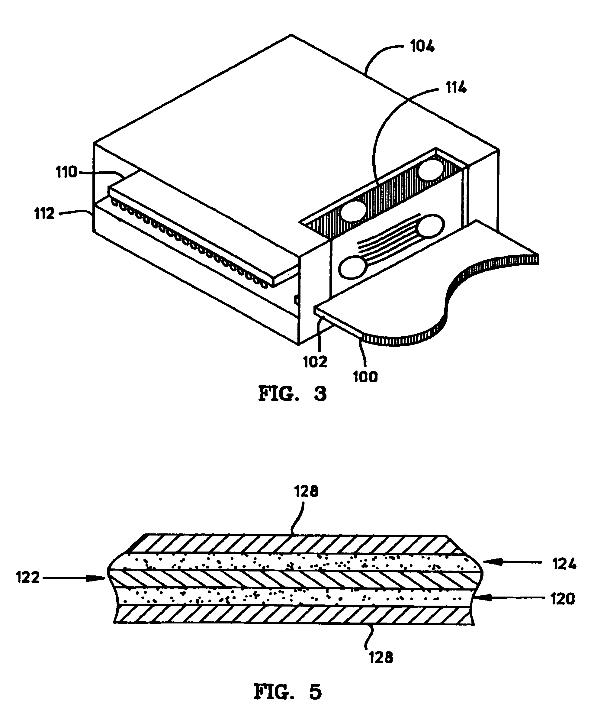
A high speed flexible interconnect cable includes a number of conductive layers and a number of dielectric layers. Conductive signal traces, located on the conductive layers, combine with the dielectric layers to form one or more high speed electrical transmission line structures. The transmission line structure may be realized as a grounded coplanar waveguide structure. The cable can be coupled to destination components using a variety of connection techniques. The cable can also be terminated with any number of known or standardized connector packages.
Description
CROSS-REFERENCE TO RELATED APPLICATIONS[0001]This application is a continuation of U.S. patent application Ser. No. 10 / 951,020 filed on Sep. 27, 2004, now U.S. Pat. No. 7,145,411, which is a continuation of U.S. patent application Ser. No. 10 / 107,667 filed on Mar. 26, 2002, now U.S. Pat. No. 6,797,891, which claims priority of U.S. Provisional Application No. 60 / 365,696, filed on Mar. 18, 2002, all of which are incorporated by reference herein.[0002]The subject matter of this application is related to the subject matter of U.S. patent application Ser. No. 10 / 107,661, titled “FLEXIBLE HIGH FREQUENCY INTERCONNECT CABLE INTEGRATED WITH A CIRCUIT SUBSTRATE,” now U.S. Pat. No. 6,797,891, and U.S. patent application Ser. No. 10 / 107,662, titled “HIGH FREQUENCY SIGNAL TRANSMISSION FROM THE SURFACE OF A CIRCUIT SUBSTRATE TO A FLEXIBLE INTERCONNECT CABLE,” now U.S. Pat. No. 6,867,668. The content of both of these applications is incorporated by reference herein.FIELD OF THE INVENTION[0003]The...
Claims
Application Information
Patent Timeline
Application Date:The date an application was filed.
Publication Date:The date a patent or application was officially published.
First Publication Date:The earliest publication date of a patent with the same application number.
Issue Date:Publication date of the patent grant document.
PCT Entry Date:The Entry date of PCT National Phase.
Estimated Expiry Date:The statutory expiry date of a patent right according to the Patent Law, and it is the longest term of protection that the patent right can achieve without the termination of the patent right due to other reasons(Term extension factor has been taken into account ).
Invalid Date:Actual expiry date is based on effective date or publication date of legal transaction data of invalid patent.

