
Wireless tracking system and method with optical tag removal detection

Active Publication Date: 2008-02-26
CENTRAK
View PDF7 Cites 73 Cited by
  • Summary
  • Abstract
  • Description
  • Claims
  • Application Information

AI Technical Summary

Benefits of technology

[0014]The present invention has recognized that tag removal in a wireless location asset tracking system complicates the asset tracking function of the system since additional components must be added to an already power exhausted and space restricted tag. The present invention is able to provide a solution that resolves the space restriction and power consumption issues.

Problems solved by technology

To the uninformed observer, the placement of transponders, also known as tags, on numerous non-stationary objects whether in an office or home would appear to be an unnecessary use of resources.
However, the uninformed observer fails to appreciate the complexity of modern life and the desire for efficiency, whether at the office or home.
However, such an assumption is sometimes erroneous due to common environmental obstacles.
Multipath effects can result in a further located receiver having a stronger signal from a tagged object than a more proximate receiver to the tagged object, which result in a mistaken location determination.
Although the prior art has provided numerous solutions to prevent the theft of goods, the prior art has yet to resolve tag removal issues associated with location asset tracking.
Further, the prior art has failed to recognize the problems associated with wireless location asset tracking.

Method used


Image

  • Wireless tracking system and method with optical tag removal detection
  • Wireless tracking system and method with optical tag removal detection
  • Wireless tracking system and method with optical tag removal detection

Examples


Embodiment Construction

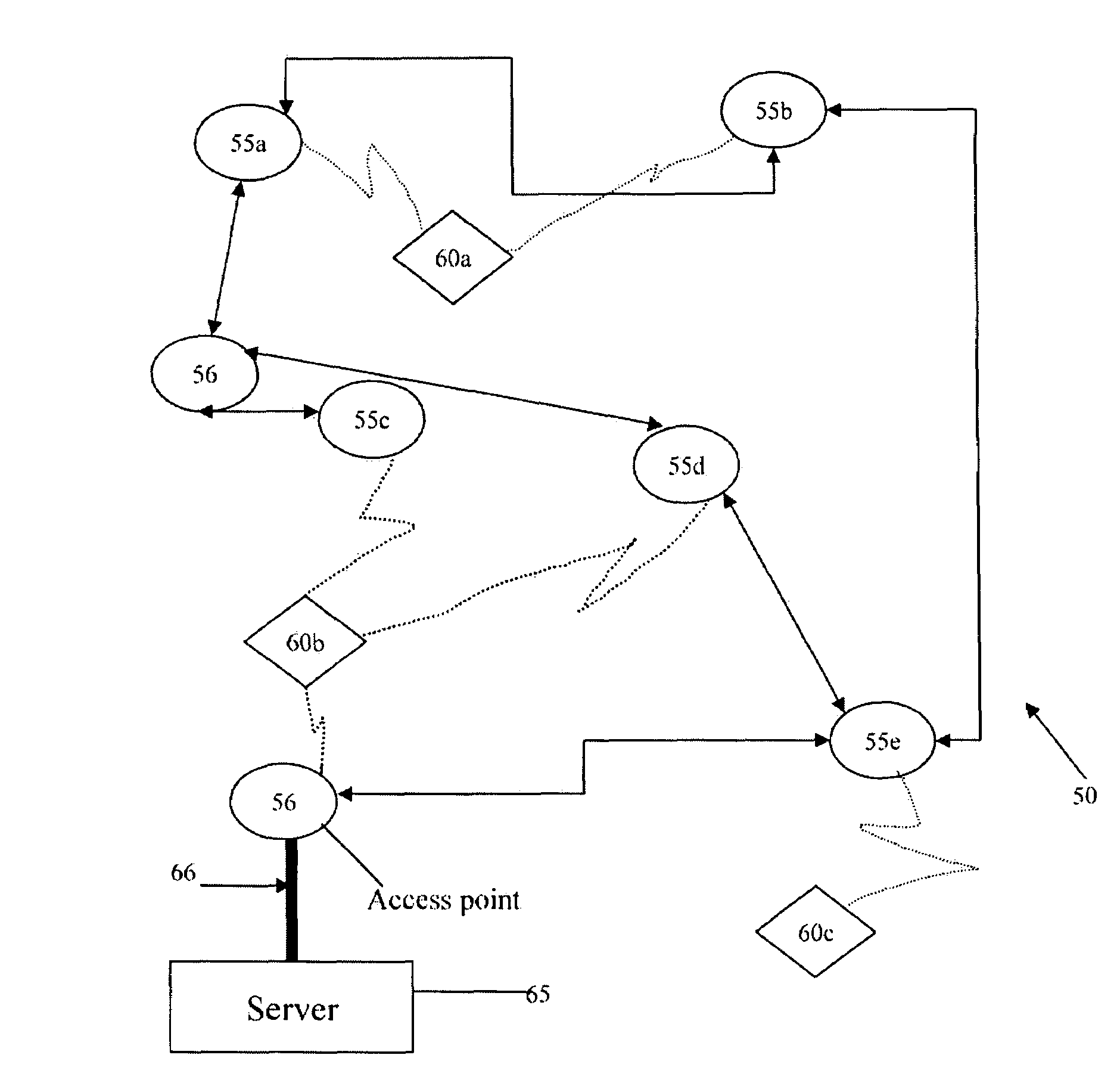
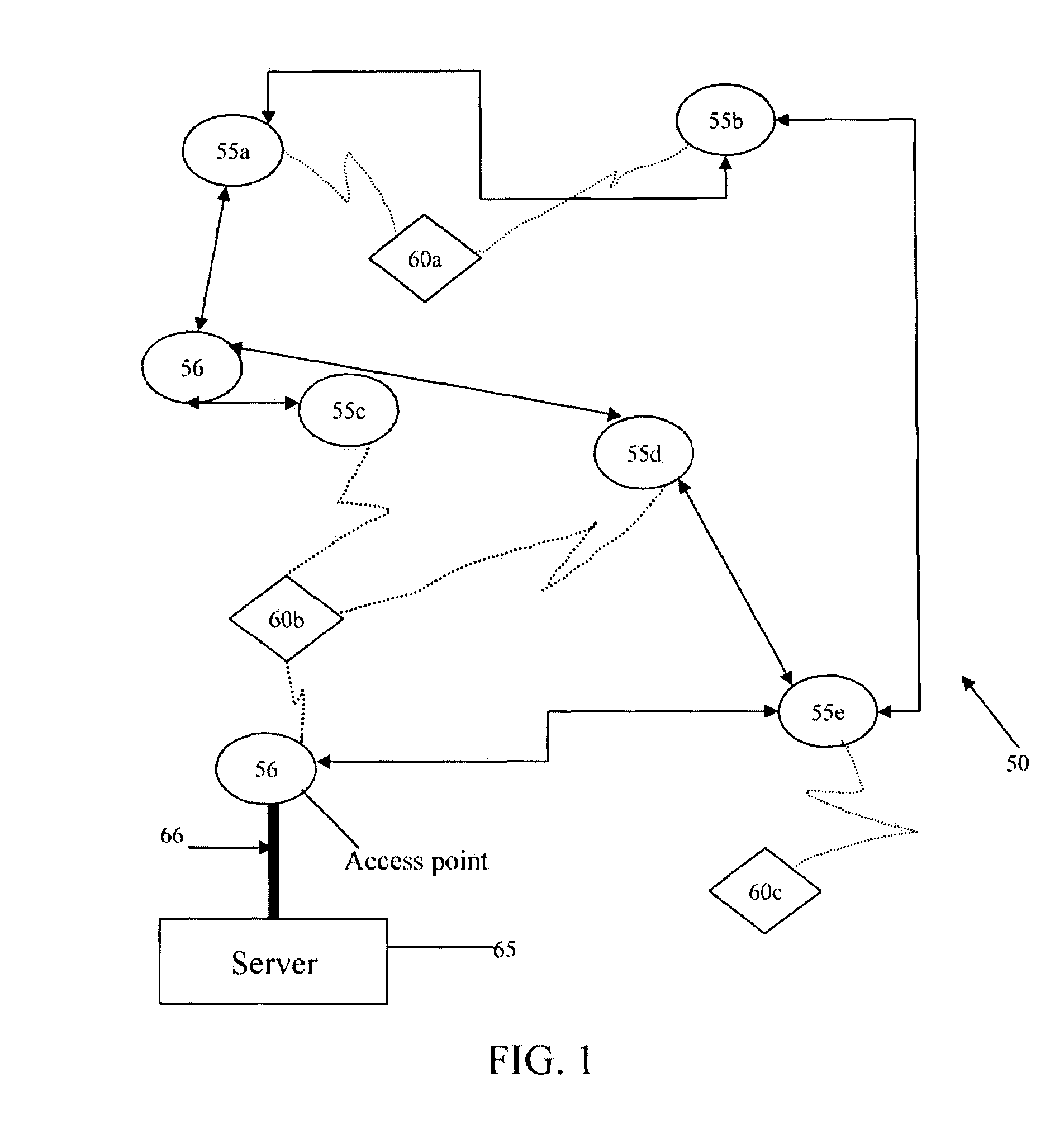
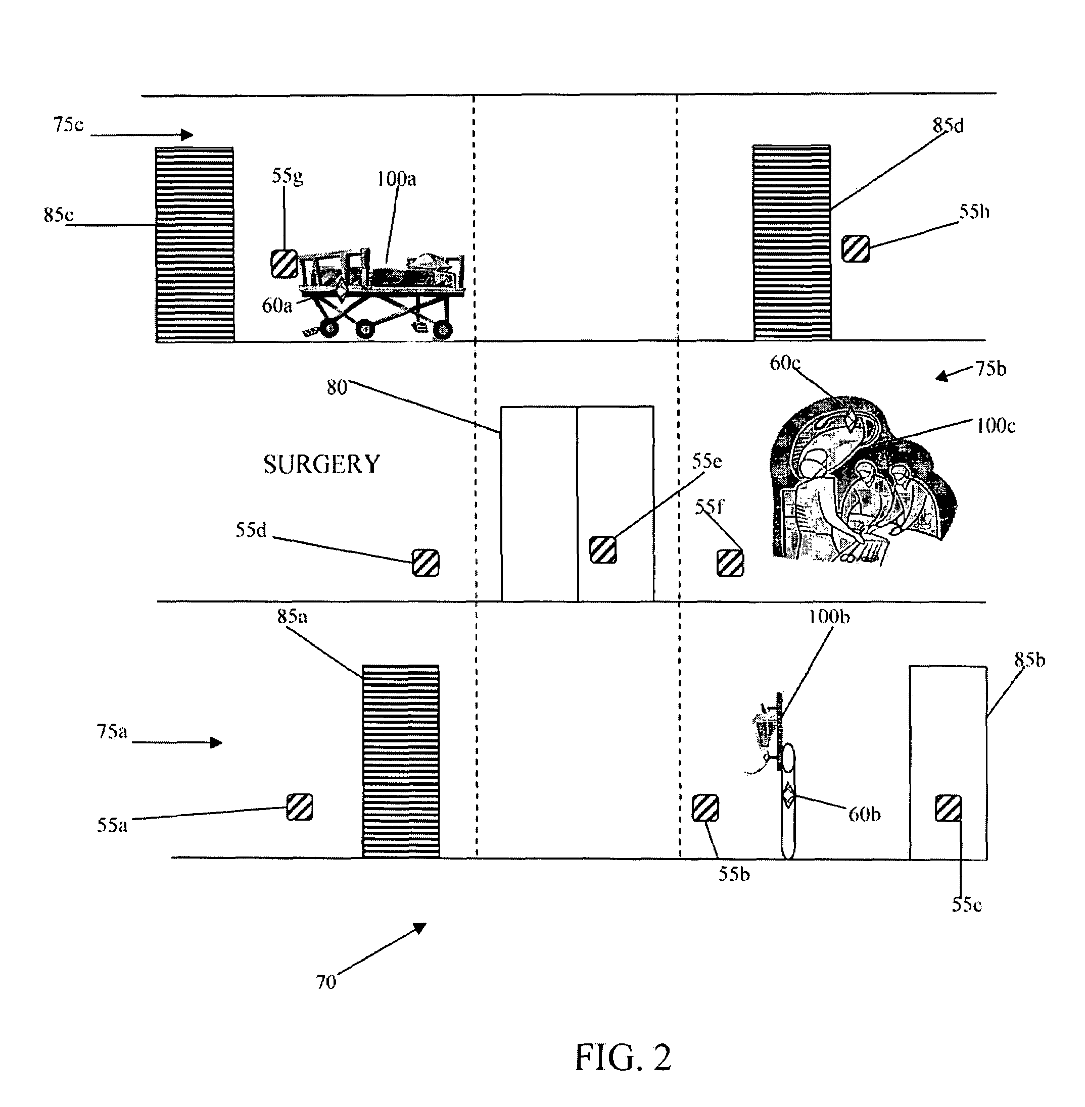
[0026]As shown in FIGS. 1-3, a wireless asset tracking system is generally designated 50. The system 50 is capable of determining real-time location of an asset 100 within an indoor facility 70. The system 50 preferably includes a plurality of sensors 55, a plurality of bridges 56, a plurality of tags 60 and at least one server 65. One example of the components of the system 50 is disclosed in U.S. patent application Ser. No. 10 / 968,814, filed on Oct. 18, 2004 for a Wireless Position Location And Tracking System which is hereby incorporated by reference in its entirety. A more specific example of the sensors 55 is disclosed in U.S. patent application Ser. No. 11 / 008,802. filed on Dec. 8, 2004 for a Plug-in Network Appliance, which is hereby incorporated by reference in its entirety. Another example of a system 50 is set forth in U.S. Pat. No. 6,751,455 for a Power-And Bandwidth-Adaptive In-Home Wireless Communications System With Power-Grid-Powered Agents And Battery-Powered Clients...


PUM


Abstract

A wireless tracking system and method with a tag removal detection feature is disclosed herein. The system and method utilize a tag attached to an asset which includes a processor, a motion sensor (such as an accelerometer), a transceiver, a tag removal sensor and a power source having a limited supply of power. The tag removal sensor is an optical sensor which is activated only when the motion sensor detects motion. In this manner, the tag conserves power since the tag is typically only in motion ten percent of the day. If the tag is removed from the asset, the optical sensor confirms the removal and an alert is activated by the system.

Description

CROSS REFERENCES TO RELATED APPLICATIONS[0001]Not ApplicableSTATEMENT REGARDING FEDERALLY SPONSORED RESEARCH OR DEVELOPMENT[0002]Not ApplicableBACKGROUND OF THE INVENTION[0003]1. Field of the Invention[0004]The present invention is related to wireless tracking systems and methods. More specifically, the present invention relates to a system and method for determining if a tracking tag has been removed from an asset.[0005]2. Description of the Related Art[0006]The ability to quickly determine the location of objects located within a facility is becoming a necessity of life. To the uninformed observer, the placement of transponders, also known as tags, on numerous non-stationary objects whether in an office or home would appear to be an unnecessary use of resources. However, the uninformed observer fails to appreciate the complexity of modern life and the desire for efficiency, whether at the office or home.[0007]For example, in a typical hospital there are numerous shifts of employee...

Claims


Application Information

Patent Timeline
IPC IPC(8): G08B13/14
CPCG08B13/1436G08B13/1481G08B13/2448
Inventor BARANOWSKI, ROBERTCALIRI, DYAMISMITH, DEREK
Owner CENTRAK
Learn More