
Bandwidth allocation for link aggregation

a technology of link aggregation and bandwidth allocation, applied in the field of data communication systems, can solve the problems of fluctuation of actual bandwidth consumed on each physical link, and service providers may not be able to provide all customers with the minimum bandwidth

Active Publication Date: 2008-02-26
ORCKIT IP LLC
View PDF26 Cites 57 Cited by
  • Summary
  • Abstract
  • Description
  • Claims
  • Application Information

AI Technical Summary

Benefits of technology

[0013]When aggregated links are used to serve a given customer, the service provider may allocate a certain fraction of the bandwidth on each of the physical links in the aggregation group so that the aggregated logical link provides the total bandwidth guaranteed by the customer's service level agreement. Typically, however, the actual bandwidth consumed on each of the physical links fluctuates statistically due to the non-uniform distr

Problems solved by technology

Typically, however, the actual bandwidth consumed on each of the physical links fluctuates statistically due to the non-uniform distribution of load among the links in the aggregation group.
Under these circumstances, the service provider may not be able to provide all customers with the minimum bandwidth guaranteed by their service level agreements.

Method used


Image

  • Bandwidth allocation for link aggregation
  • Bandwidth allocation for link aggregation
  • Bandwidth allocation for link aggregation

Examples


Embodiment Construction

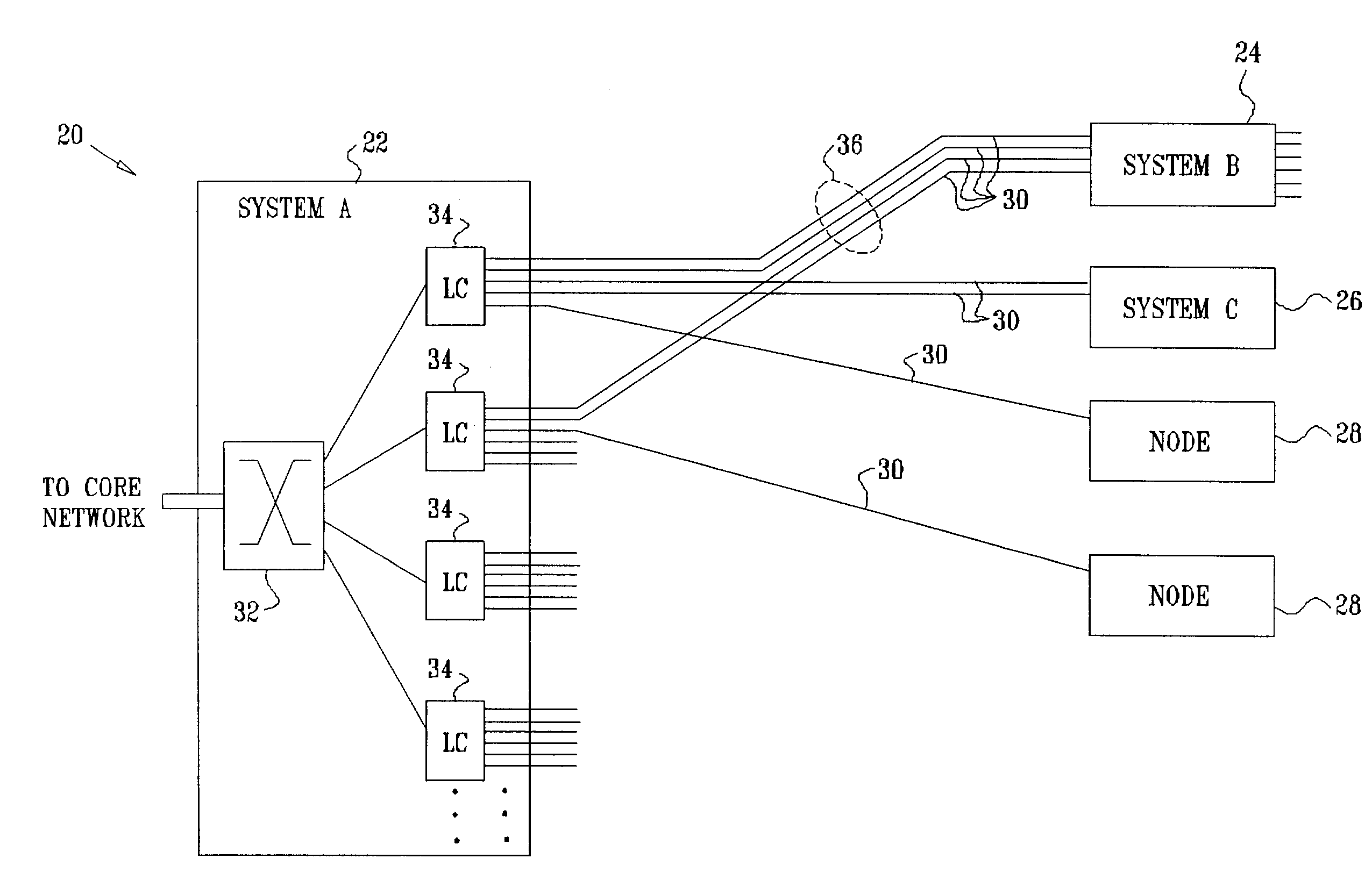
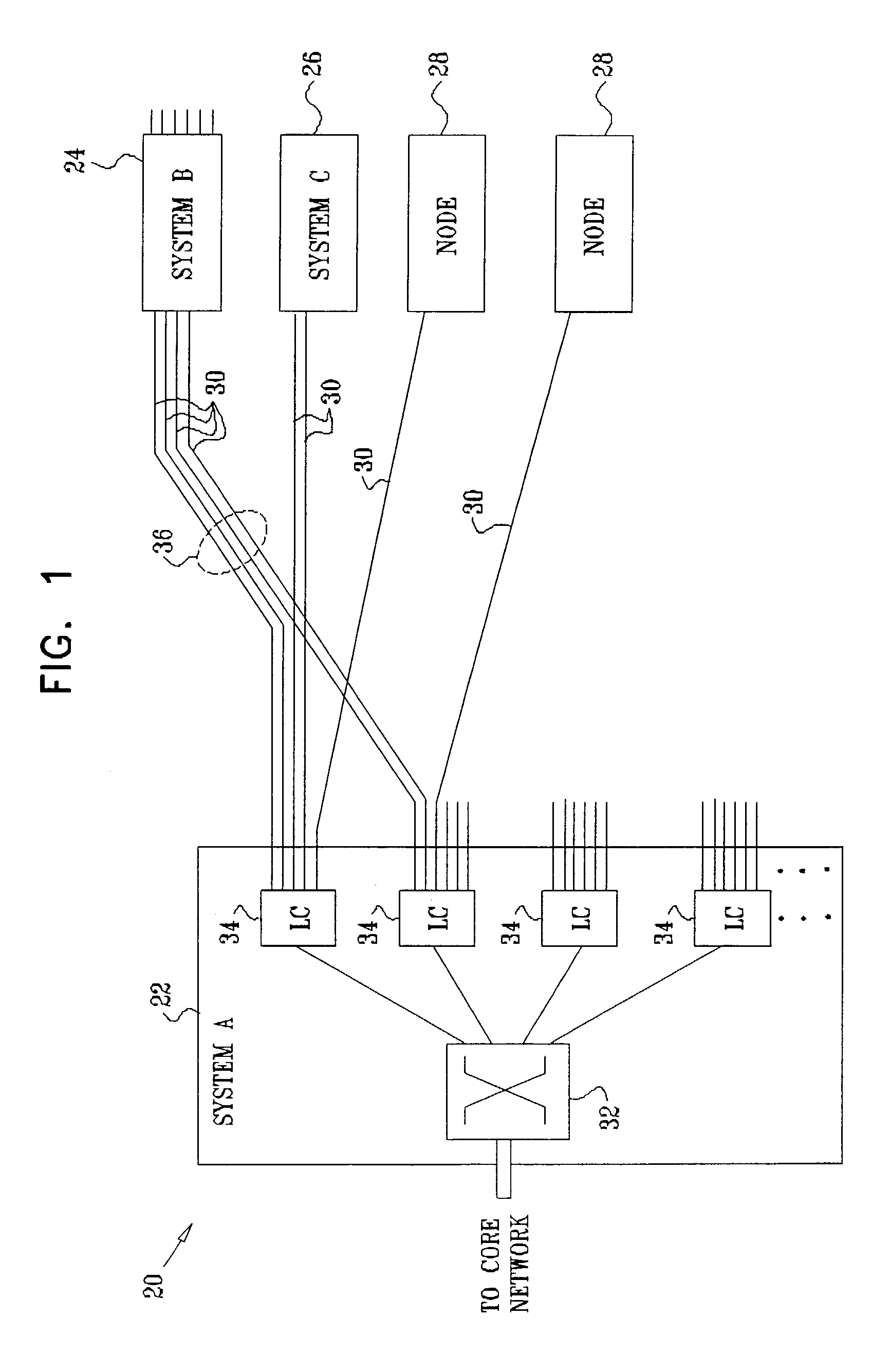
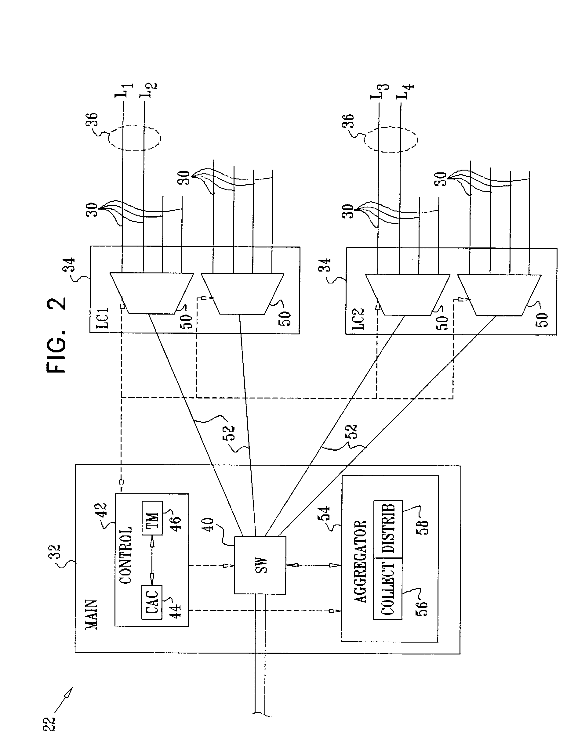
[0046]FIG. 1 is a block diagram that schematically illustrates elements of a communication system 20, in accordance with an embodiment of the present invention. In this example, central office equipment 22 communicates with customer nodes 24, 26, 28, . . . , over physical links 30. Links 30 typically comprise full-duplex Ethernet links, such as 10BASE-n, 100BASE-n or Gigabit Ethernet links, as are known in the art. (Alternatively, as noted above, other types of physical links may be used, such as ATM or PPP links.) Equipment 22 is configured to convey packet data traffic between the customer nodes and a network (which may be a metro network, access network, or other type of core network, for example). For this purpose, equipment 22 comprises a main switching card 32, which is connected to multiple line cards 34 that serve links 30. Details of the structure and operation of equipment 22 are shown below in FIG. 2 and are described with reference thereto.

[0047]Equipment 22 and certain ...


PUM


Abstract

A method for establishing a connection with a guaranteed bandwidth for transmitting data over a logical link that includes a plurality of parallel physical links between first and second endpoints. A link bandwidth is allocated on each of the physical communication links so as to include a predefined safety margin, based on either a failure protection policy, or a measure of fluctuation that occurs in a rate of data transmission over the physical links, or both. A sum of the allocated link bandwidth over the plurality of the parallel physical links is substantially greater than the guaranteed bandwidth of the connection. The data are conveyed over the logical link by distributing the data for transmission among the physical links in accordance with the allocated link bandwidth.

Description

FIELD OF THE INVENTION[0001]The present invention relates generally to data communication systems, and specifically to methods and systems for link aggregation in a data communication network.BACKGROUND OF THE INVENTION[0002]Link aggregation is a technique by which a group of parallel physical links between two endpoints in a data network can be joined together into a single logical link. Traffic transmitted between the endpoints is distributed among the physical links in a manner that is transparent to the clients that send and receive the traffic. Link aggregation offers benefits of increased bandwidth, as well as increased availability, since the logical link can continue to function (possibly with reduced bandwidth) even when one of the physical links fails or is taken out of service.[0003]For Ethernet networks, link aggregation is defined by Clause 43 of IEEE Standard 802.3, Carrier Sense Multiple Access with Collision Detection (CSMA / CD) Access Method and Physical Layer Specif...

Claims


Application Information

Patent Timeline
IPC IPC(8): H04J13/06H04J1/16H04L12/56
CPCH04L47/10
Inventor BRUCKMAN, LEONMOR, GALMENAHEMI, ZVI
Owner ORCKIT IP LLC
Learn More