Shaping apparatus, communication node and flow control method for controlling bandwidth of variable length frames

a traffic shaping and variable-length frame technology, applied in the field of traffic shaping apparatus, communication nodes and flow control methods for controlling the bandwidth of variable-length frame, can solve the problems of inability to guarantee stable bandwidth per user, inability to ensure stable quality service, temporary channel occupation by a particular user, etc., to prevent excess of maximum allowed bandwidth

Inactive Publication Date: 2005-11-24
HITACHI LTD
View PDF2 Cites 17 Cited by
  • Summary
  • Abstract
  • Description
  • Claims
  • Application Information

AI Technical Summary

Benefits of technology

[0025] Further, by fixing the level count lower limit that decides on the timing to generate the first frame output request based on the maximum allowed bandwidth to the threshold value, continuous issuance of frame output requests due to level count decrement lower than the threshold can be inhibited even in a situation, ...

Problems solved by technology

However, a stable bandwidth per user is not guaranteed and temporary channel occupation by a particular user ...

Method used


Image

  • Shaping apparatus, communication node and flow control method for controlling bandwidth of variable length frames
  • Shaping apparatus, communication node and flow control method for controlling bandwidth of variable length frames
  • Shaping apparatus, communication node and flow control method for controlling bandwidth of variable length frames

Examples


first embodiment

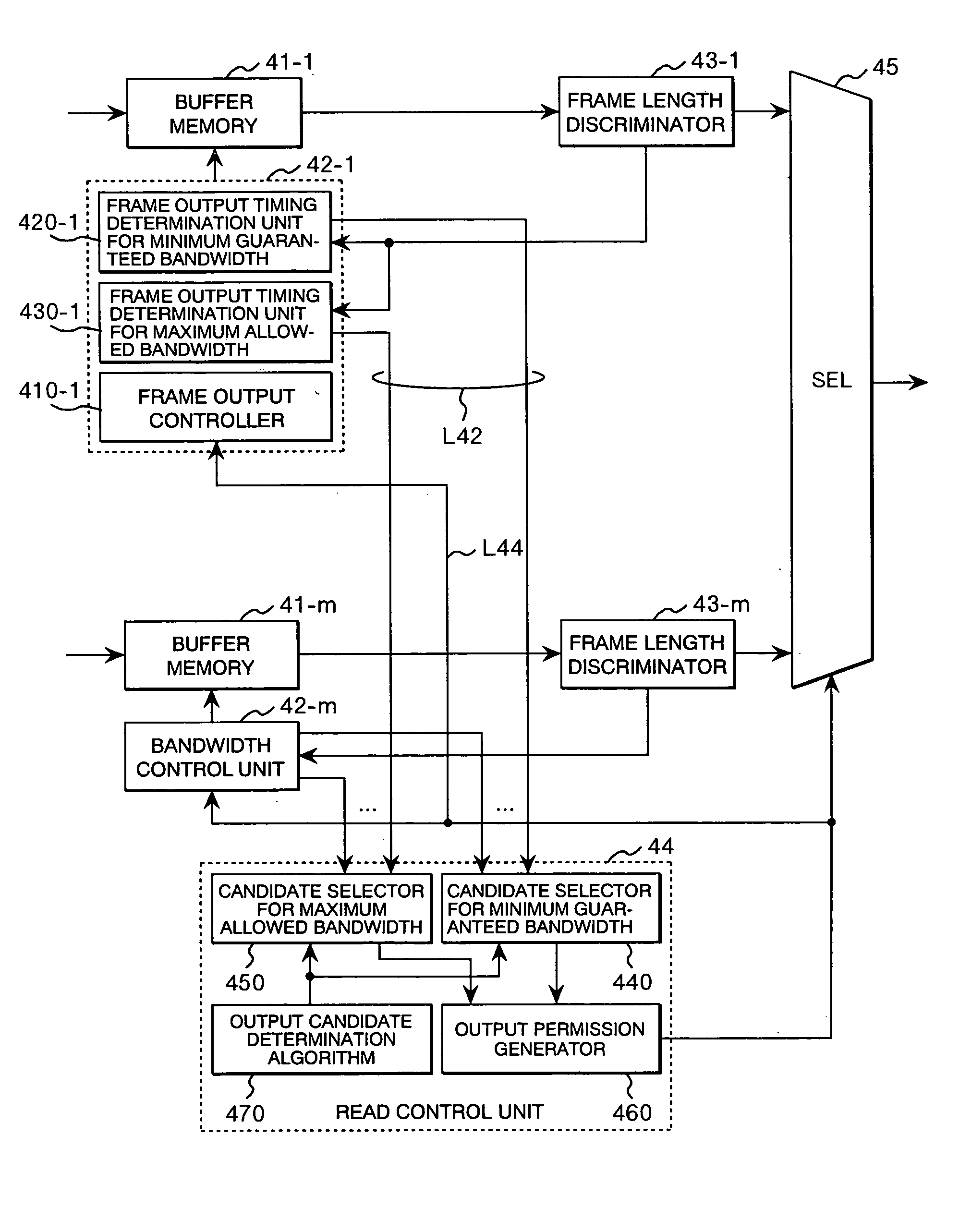
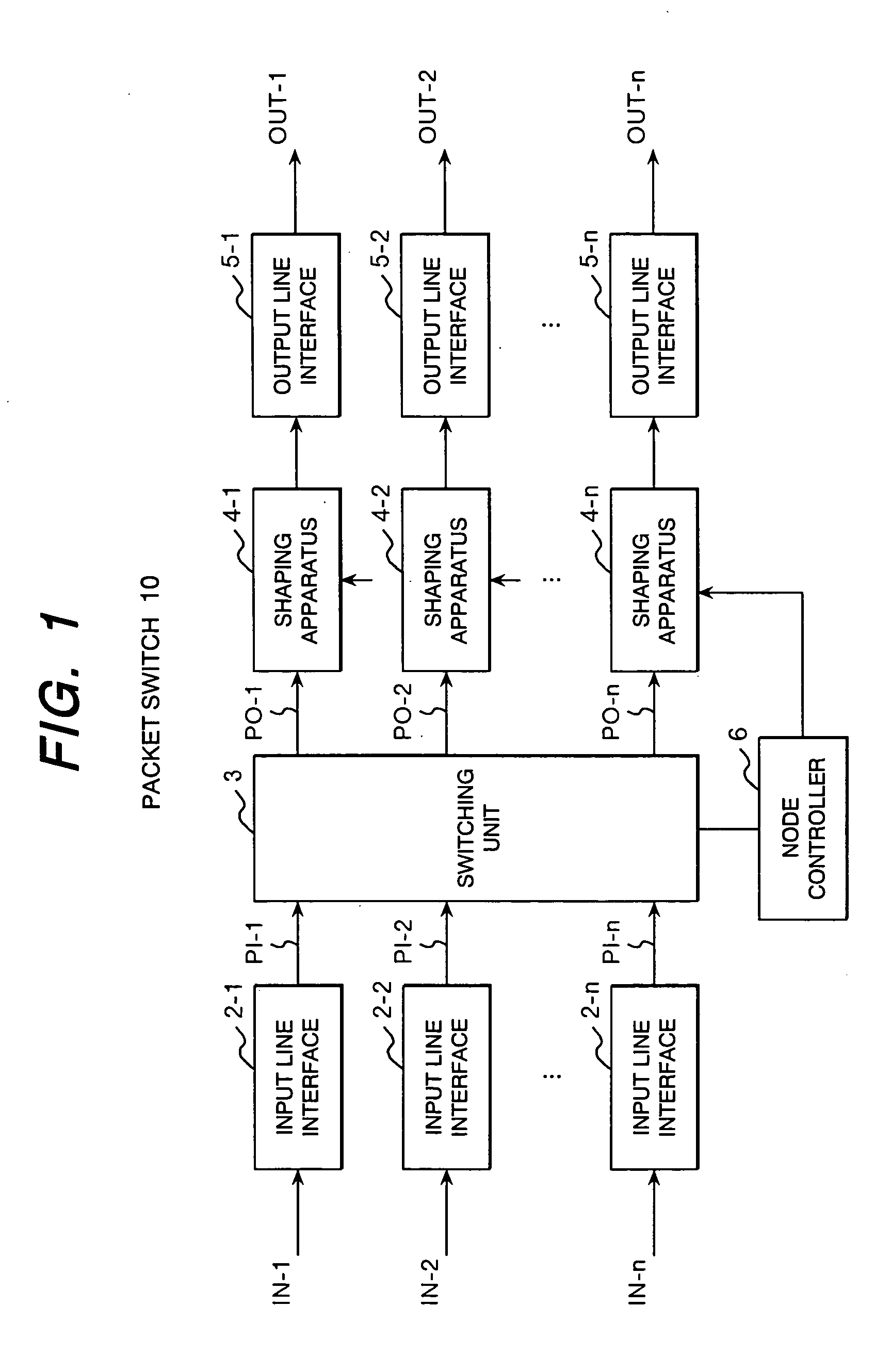
[0042]FIG. 3 shows a shaping apparatus 4-i of the present invention to be connected to an output port PO-i of the switching unit 3.

[0043] The shaping apparatus 4-i is comprised of a frame distribution unit 400 connected to the output port PO-i of the switching unit 3, a plurality of flow control units 40 (40-1 to 40-m) connected to the frame distribution unit 400, a read control unit 44 and a selector 45 each connected to these flow control units 40.

[0044] Each of the flow control units 40 includes a buffer memory 41 (41-1 to 41-m) for temporarily storing output frames (packets) each belonging to one of flows on the flow-by-flow basis, a bandwidth control unit 42 (42-1 to 42-m) associated with the buffer memory, and a frame length discriminator 43 (43-1 to 43-m) which detects the length of a frame read out from the buffer memory and notifies the bandwidth control unit 42 of the frame length.

[0045] An output frames transferred to the output port PO-i through the switching unit 3 is...

second embodiment

[0085]FIG. 8 shows a shaping apparatus according to the present invention.

[0086] The shaping apparatus shown in the second embodiment is comprised of a plurality of first stage shaping units 401 (401-1 to 401-m) prepared for each group and a second stage shaping unit 402 connected between these first stage shaping units and an output line interface. Output frames transferred through the switching unit 3 to an output port PO-i are distributed to the first shaping units appropriately by the frame distribution unit 400 shown in FIG. 3.

[0087] Each of the first stage shaping units 401 is comprised of a plurality of first flow control units 410 (410-1 to 410-k), each of which stores temporarily variable length frames each belonging to one of flows in the same group and determines timing to output each of the buffered frames in accordance with a maximum allowed bandwidth and a minimum guaranteed bandwidth which have been preset for each flow, a first read control unit 440 connected to the...


PUM


Abstract

A shaping apparatus comprising a plurality of buffer memories allocated for different flows, bandwidth control units associated with the buffer memories, and a read control unit, wherein each of the bandwidth control units issues a first frame output request based on a maximum allowed bandwidth and a second frame output request based on a minimum guaranteed bandwidth, and the read control unit selects a bandwidth control unit to be permitted for frame output execution out of bandwidth control units that are issuing the first or second frame output request, giving priority to the second frame output request.

Description

CLAIM OF PRIORITY [0001] The present application claims priority from Japanese patent application serial No. 2004-151666, filed on May 21, 2004, the content of which is hereby incorporated by reference into this application. BACKGROUND OF THE INVENTION [0002] (1) Field of the Invention [0003] The present invention relates to a traffic shaping apparatus, a communication node and a flow control method for sending out bandwidth controlled variable length frames. [0004] (2) Description of Related Art [0005] Recently, there is an increasing demand for high-speed networks such as broadband services. As one form of high-speed networks, Ethernet base networks that provide low cost communication have wide dissemination. In the Ethernet-base networks, best-effort based communication services in which an allocated bandwidth is determined subject to channel availability are provided, which is suitable for burst packet transmission with a high peak rate. However, a stable bandwidth per user is n...

Claims


Application Information

Patent Timeline
IPC IPC(8): H04L47/22H04L12/28H04L47/21
CPCH04L47/10H04L47/22H04L47/21H04L47/13
Inventor SHINAGAWA, TAISHIKOBAYASHI, MASANOBUASHI, YOSHIHIROKAZAWA, TORU
Owner HITACHI LTD
Why Eureka
Try Eureka