Insulated ceiling hatch

Inactive Publication Date: 2008-03-04
C & E ENTERPRISES INC
View PDF30 Cites 8 Cited by
  • Summary
  • Abstract
  • Description
  • Claims
  • Application Information

AI Technical Summary

Benefits of technology

[0013]When the hatch is closed, the insulating block resides substantially within the passage, and the bottom surface is aligned with the lower edge of the frame. When the hatch is open, the insulating block has been pivoted to a position where it is removed from the passage, and a user can pass through the passage. By connecting the insulating block to the frame with a hinge, the insulating block is guided into the passage when the hatch is closed by the user, facilitating closure of the hatch.
[0014]The insulating block is preferably configured such that a substantial portion of the side surface of the insulating block resides in contact with or in close proximity to the sidewall of the frame when the hatch is closed. Providing, on the average, a small separation S between the insulating block and the frame serves to impede air flow therebetween. Preferably, the separation S is maintained less than about ⅛″ over a substantial portion of the side surface and the sidewall. The separation S is more preferably maintained at about 1/16″, but providing such close spacing between the side surface of the insulating block and the sidewall of the frame may make fabrication of the hatch more difficult.
[0015]To reduce leakage of air between the side surface of the insulating block and the sidewall of the frame when the hatch is closed, it is preferred to provide means for sealing the passage with respect to the insulating block. These means can be provided by having the sidewall of the passage and side surfaces of the insulating block configured to engage such that a seal is created therebetween. Alternatively, when a rim is employed which extends under the periphery of the passage so as to form a lip, the means for sealing can be provided by the engagement of the bottom surface of the insulating block with the lip. Alternatively, weatherstripping can be applied to the sidewall and/or to the insulating block to seal the passage. It is preferred that the weat

Problems solved by technology

However, when a hatch is installed in the ceiling to provide access to the attic space, the hatch interrupts the ceiling and can allow increased air infiltration between the occupied areas and the attic, reducing the insulating properties of the ceiling.
These caps are bulky and may be difficult for a user to reinstall properly when exiting the attic space.
While these hatches provide ease of use, the thickness of insulation that can be provided on the doors of these hatches is very limited, particularly when the door also serves as a support for fold-down stairs.
Even when such stairs are not employed, the thickness of insulation is limited since the insulation extends into and partially obstructs the hatch opening when the door hangs open.
A further limitation to all these downwardly-opening hatches is

Method used


Image

  • Insulated ceiling hatch
  • Insulated ceiling hatch
  • Insulated ceiling hatch

Examples


Embodiment Construction

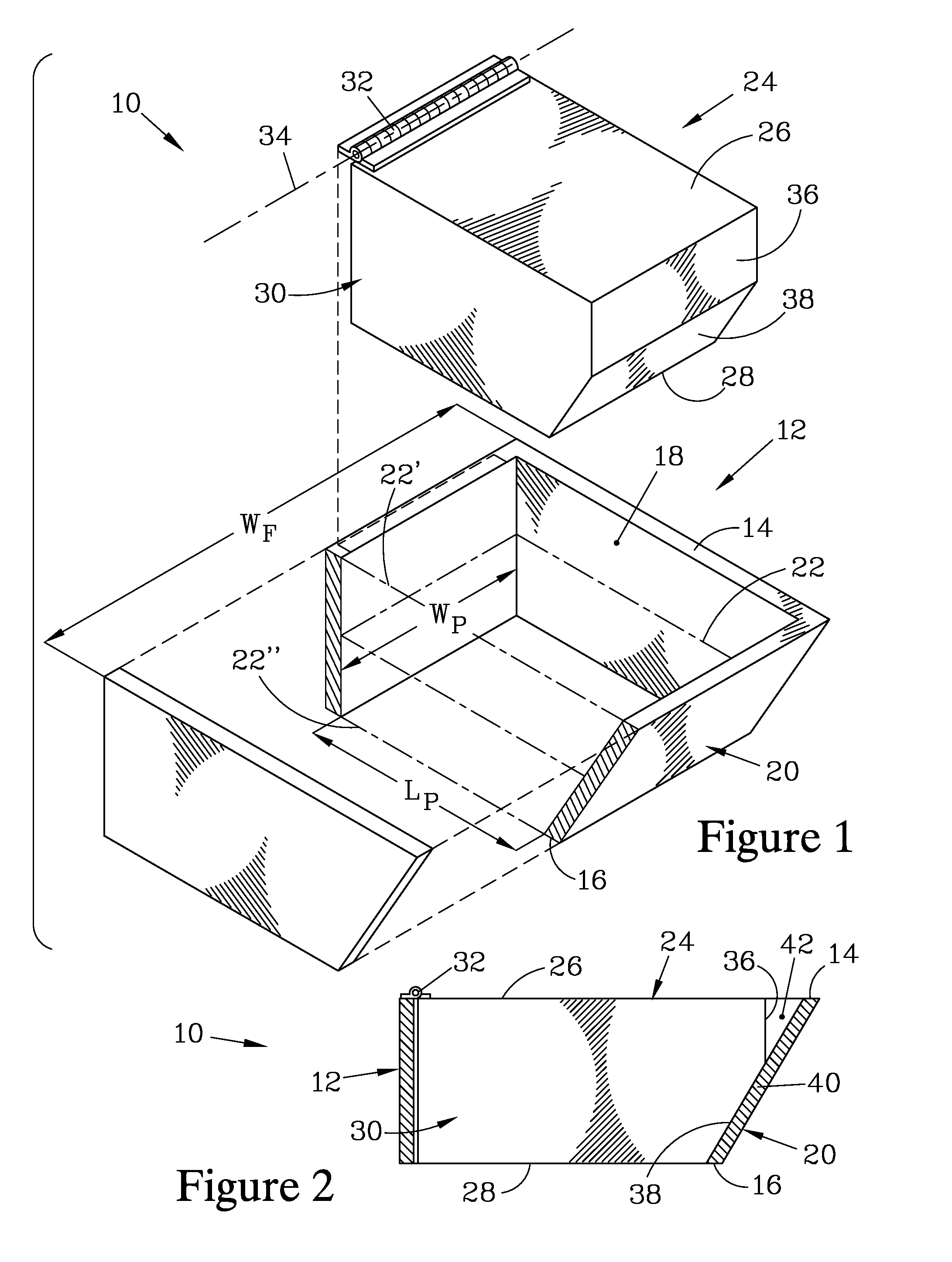
[0028]FIG. 1 is a partially sectioned and exploded isometric view of a ceiling hatch 10 that forms one embodiment of the present invention. The ceiling hatch 10 has a frame 12 which terminates in an upper edge 14 and a lower edge 16, and has a passage 18 that extends between the upper edge 14 and the lower edge 16. The passage 18 is bounded by a sidewall 20. The passage 18 is further configured such that it has a cross section 22 which decreases as the passage 18 traverses from the upper edge 14, where the cross section 22′ is greatest, to the lower edge 16, where the cross section 22″ has reached its minimum cross section and defines a passage minimum width WP and a passage minimum length LP.

[0029]For installation in a ceiling having rafters spaced on 24 inch (61 cm) centers, which is typical for residential construction, the frame 12 preferably has a frame width WF less than 22½ inches (57 cm) so that the frame 12 can slide between two adjacent rafters and be attached thereto. How...


PUM


Abstract

A ceiling hatch employs a frame having an upper edge and a lower edge and a passage bounded by a sidewall passing therebetween, the passage extending from the lower edge to the upper edge and having its minimum cross section at the lower edge. This frame is employed with an insulating block bounded by a top surface, a bottom surface and a side surface, and which is configured to be positionable substantially within the passage and substantially filling the same. A hinge attaches the frame to the insulating block, providing pivotable action between the insulating block and the frame about a pivot axis and allowing the insulating block to be swung out of the passage on an interference-free path such that the bottom surface of the insulating block is in a horizontal plane when the insulating block resides substantially within the passage.

Description

[0001]This application claims priority of Provisional Application No. 60 / 456,511 filed Mar. 24, 2003.FIELD OF THE INVENTION[0002]The present invention relates to hatches for allowing access to an area located above a ceiling, and more particularly to a hatch which provides both ease of use and high resistance to heat loss.BACKGROUND OF THE INVENTION[0003]Ceilings that separate occupied areas of a building from an attic area residing above the ceiling serve to reduce heat loss and associated energy costs by providing a trapped region of air in the attic space that serves as an insulator. The reduction of heat loss can be increased by covering the ceiling with an insulating material. However, when a hatch is installed in the ceiling to provide access to the attic space, the hatch interrupts the ceiling and can allow increased air infiltration between the occupied areas and the attic, reducing the insulating properties of the ceiling. This reduction in insulation of the ceiling is exac...

Claims


Application Information

Patent Timeline
IPC IPC(8): E02D29/14E06B1/04E04F11/06
CPCE04F11/06
Inventor VIENS, CHRISTOPHER P.
Owner C & E ENTERPRISES INC
Why Eureka
Try Eureka