Dental implant system

a technology applied in the field of dental implants and abutments, can solve the problems of difficult rotational alignment, difficult thread connection, and difficult thread bore operation,

Active Publication Date: 2008-03-04
BIOMET 3I LLC
View PDF306 Cites 114 Cited by
  • Summary
  • Abstract
  • Description
  • Claims
  • Application Information

AI Technical Summary

Benefits of technology

[0022]An abutment screw is adapted to fit within a through-bore extending through the post and stem of the abutment and retain to the abutment in the implant. The abutment screw comprises a proximal end (e.g., the screw head) adapted to interface with the abutment and a distal end adapted to engage the threaded section of the implant. More generally, the implant may be provided with an internal axial retention section adapted to engage an abutment retention shaft. The axial retention shaft engages an internal axial retention feature of the implant to limit axial movement of the abutment relative to the implant.

Problems solved by technology

This latter scenario can be more complicated due to the added connection between the implant and the abutment.
Rotational alignment is not, however, easily achieved using threaded connections.
Further, such a threaded bore, by itself, cannot generally provide rotational fixing.
These designs are not, however, free of problems.
An inherent disadvantage of implant components is that their small size makes assembly difficult.
Problems include the difficulty of properly positioning abutments in implants.
The relatively small size of the components and tight working environment make it difficult to know when an abutment is properly seated in an implant.
Related problems include abutments becoming loose due to the extreme forces incurred through normal chewing actions.
Practitioners have noted that some abutments used in these screwless systems become loose due to the large forces generated through chewing.
For some, the disadvantages associated with screwless abutments outweigh any potential benefits.
These screwless abutments also exhibit unacceptable axial movement.
This axial movement can lead to damage of the abutment or the implant as a result of misaligned forces and increased internal wear.
The internal wear and misaligned forces lead to further unacceptable movement, inevitably requiring repair and replacement.
In the mildest cases, the patient is inconvenienced.
In the more severe cases, where the patient waits too long, infection and permanent bone and tissue damage occur.
But not all disadvantages have been overcome, and some solutions carry their own disadvantages.

Method used


Image

  • Dental implant system
  • Dental implant system
  • Dental implant system

Examples


Embodiment Construction

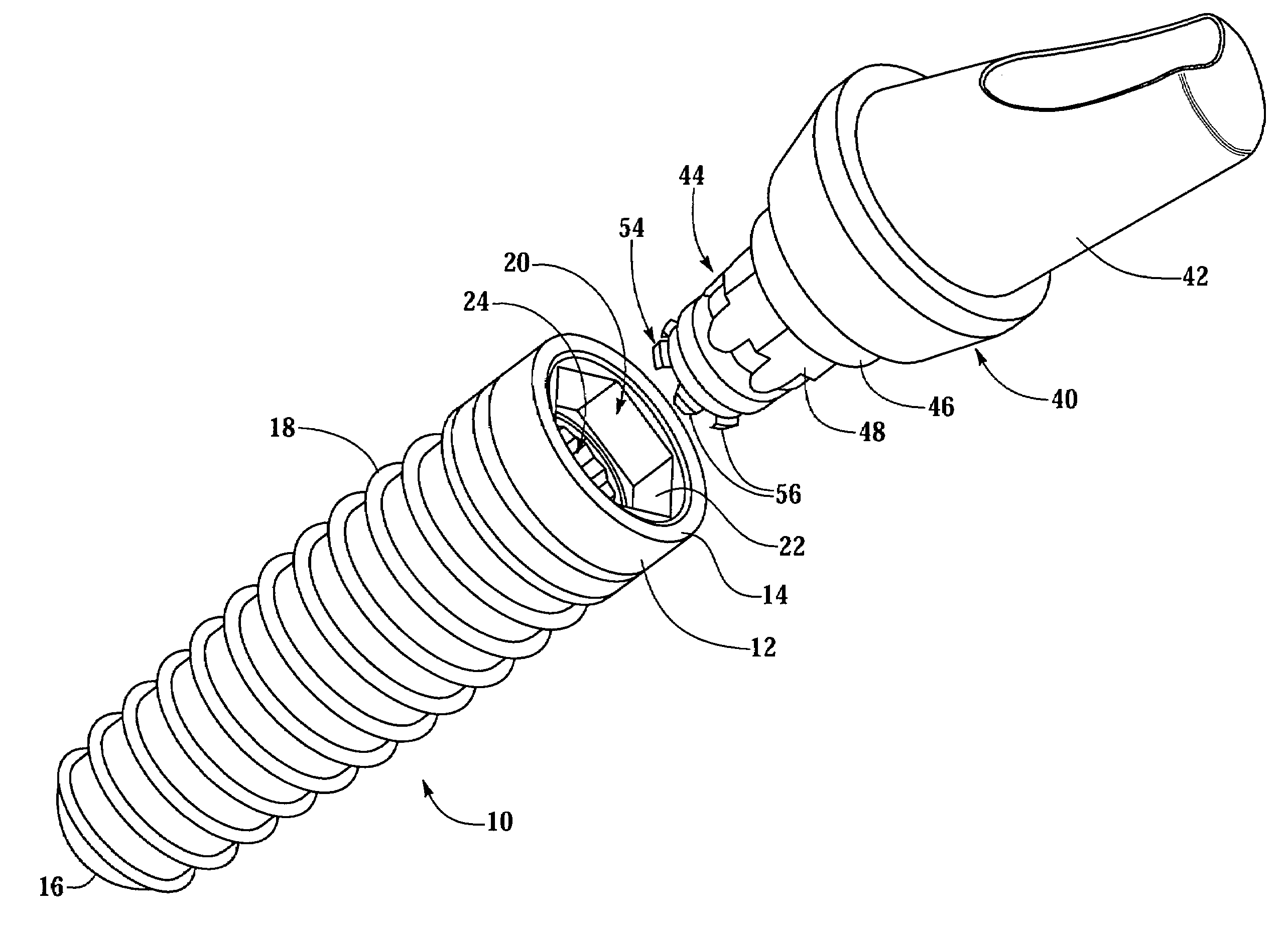
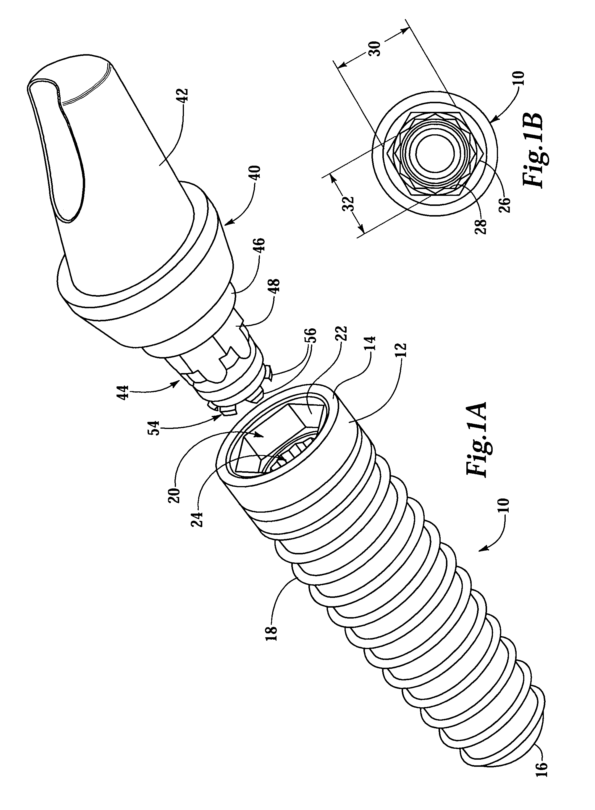
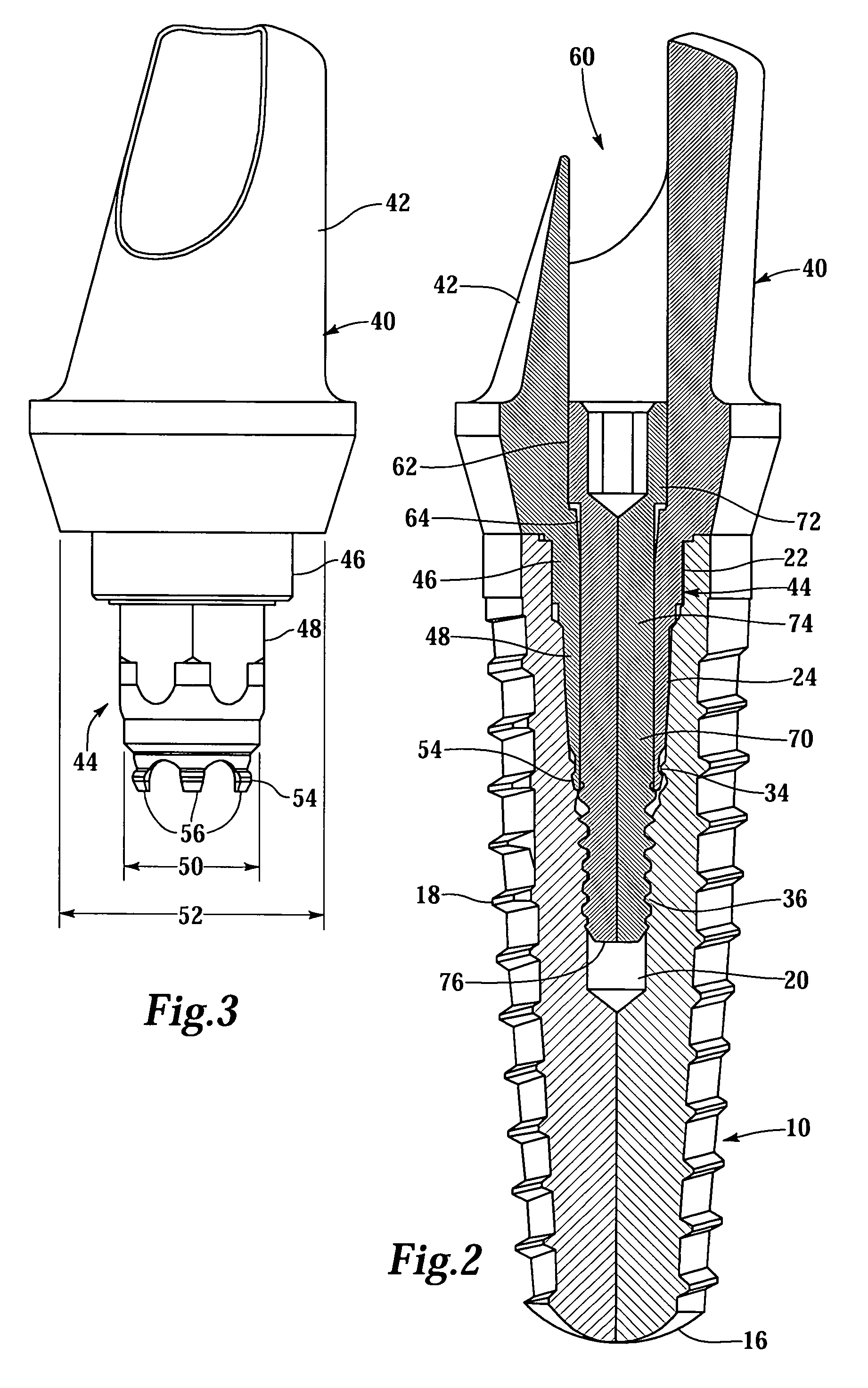
[0036]FIGS. 1 and 2 illustrate an implant 10 adapted to be screwed into the bone of a patient and an abutment 40 adapted to be connected to the implant 10. The implant 10 comprises a proximal end 12 including a table 14 adapted to abut the abutment 40. The implant 10 comprises a distal end 16 opposite the proximal end 12 and at least one thread 18 disposed therebetween for screwing the implant 10 into the bone of a patient. An interior bore 20 extends distally from the proximal end 12 toward the distal end 16. The interior bore 20 comprises a first anti-rotation cavity 22 and a second anti-rotation cavity 24 distal of the first anti-rotation cavity 22.

[0037]In FIG. 1, the two cavities 22 and 24 are separate, distinct and slightly spaced apart, and are connected with a tapered section. Other arrangements, however, are equally suitable, such as, for example, where the cavities are adjacent and step-wise connected, or spaced apart and connected by one or more cavities.

[0038]Focusing on...


PUM


Abstract

An implant comprising two internal anti-rotational features. One anti-rotational feature is adapted to engage a driving tool, while the other anti-rotational feature is adapted to engage an abutment. An implant abutment system is provided with an angled abutment adapted to mate with one of the anti-rotational features. A second, straight abutment is adapted to engage with the other anti-rotational feature. An abutment is provided with resilient fingers to interface with the implant and provide tactile and audible feedback indicating when the abutment is properly seated. An abutment screw extends through the abutment and engages the implant bore distal of the stem of the abutment. The abutment screw limits axial movement of the abutment relative to the implant. A driving tool comprising one of at least retention structure and visual alignment indicia is provided to facilitate screwing the implant into a patient's bone.

Description

RELATED APPLICATIONS[0001]This application is based on U.S. Provisional Application No. 60 / 450,541, filed Feb. 26, 2003; which is based on U.S. Provisional Application No. 60 / 425,976, filed Nov. 13, 2002.FIELD OF THE INVENTION[0002]This invention relates to dental implants and abutments and related articles.BACKGROUND OF THE INVENTION[0003]Single tooth restorations present the unique requirement that they must be supported non-rotationally on the underlying abutment. When a prepared natural tooth is the underlying abutment, this requirement is met in the normal course of preparing the abutment with a non-circular cross-section. Likewise, when the underlying abutment is a post fitted onto an implant, this requirement is met by preparing the post with a noncircular cross-section. This latter scenario can be more complicated due to the added connection between the implant and the abutment.[0004]Typically, a dental implant is implanted into the bone of a patient's jaw and comprises a so...

Claims


Application Information

Patent Timeline
Patent Type & Authority Patents(United States)
IPC IPC(8): A61C8/00
CPCA61C8/0001A61C8/005A61C8/006A61C8/0066A61C8/0069A61C8/0089A61C8/008A61C8/0065A61C8/0056A61C8/0057A61C8/0059A61C2008/0084A61C8/0068A61C8/00
Inventor PORTER, STEPHAN S.ROGERS, DAN P.GOODMAN, RALPH E.
Owner BIOMET 3I LLC
Why Eureka
Try Eureka