
Valve mechanism for a vacuum valve

a vacuum valve and valve mechanism technology, applied in the direction of valve details, slide valves, engine components, etc., can solve the problems of high cost of realizing such a solution, inability to bear as much stress on the support shaft, and ineffective system overall, etc., to achieve high sealing force, equal force transmission capability, and high load bearing capability

Active Publication Date: 2008-03-11
BOSCH HUBERT
View PDF20 Cites 23 Cited by
  • Summary
  • Abstract
  • Description
  • Claims
  • Application Information

AI Technical Summary

Benefits of technology

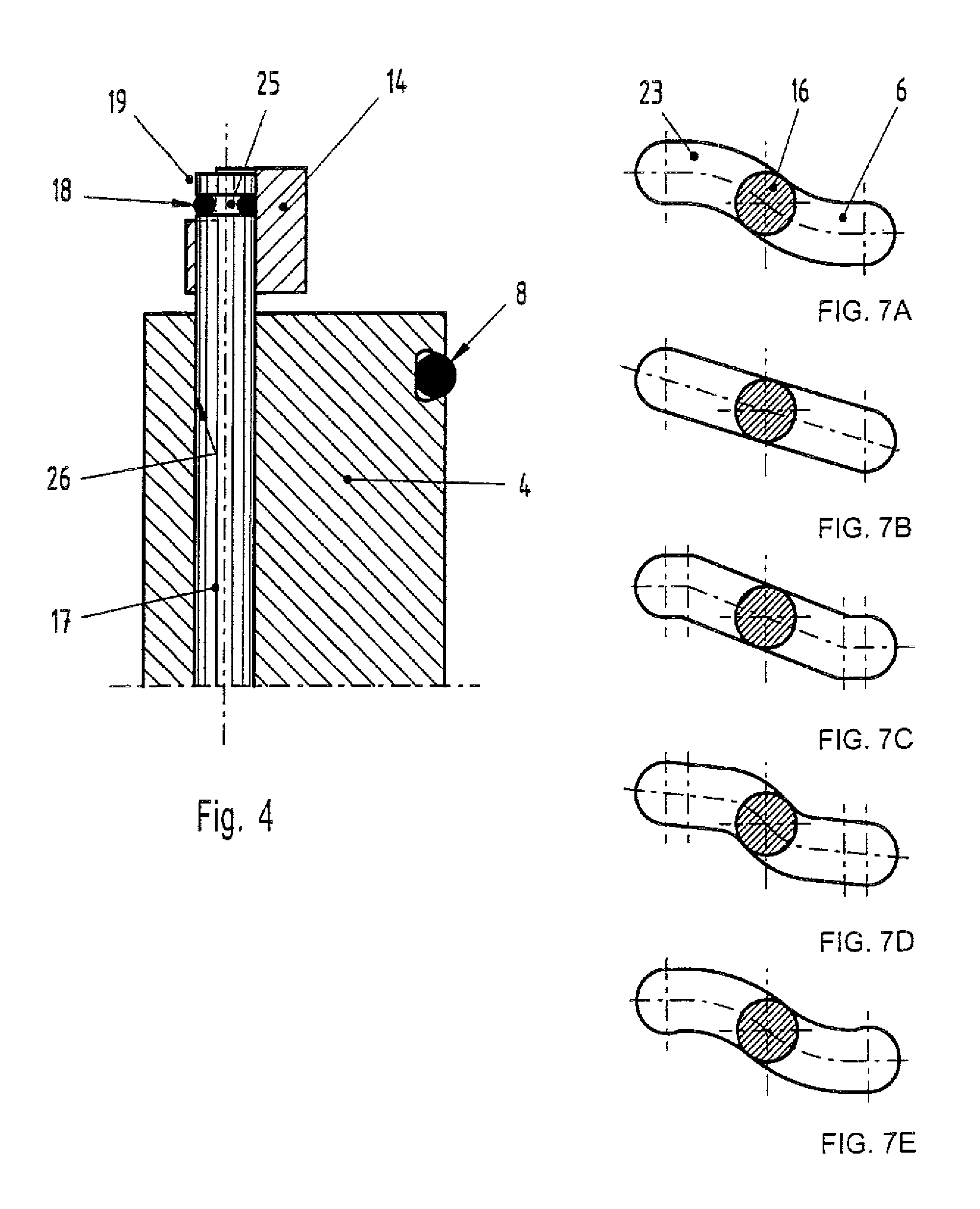
[0010]Another advantage of the present invention is that the cooperating slots in the one piece and the neighboring piece are both closed, so that the roll bodies are secured against undesirable displacement (or dislodgment) upward or downward or otherwise. The closed slots limit engagement of the roll bodies to the axial longitudinal direction.
[0011]The roll bodies disclosed here are not self-supported bearings, such as ball bearings with inner and outer races, but are free guided roll bodies without the use of additional mechanical elements. Accordingly, for a given external diameter they have appreciably higher load bearing capability. This leads to the advantage that a closed slot in accordance with the invention has equal force transmission capability and equal force sustaining capability, in both the closing and the opening operations. This enables the invention to have very high sealing forces and very high releasing forces. Such releasing forces may also be required if, after a very long period of being closed, the seal, which generally will be an elastomeric seal, has developed substantial adhesion forces which must be overcome in the opening operation.
[0012]A particular advantage of the invention is that in the simplest case no tensile return springs are needed, because the roll bodies are completely forced and guided, and enclosed, in associated accommodating configurations between the slots, and are forcibly guided in the valve-sealing direction and in the opposite direction.
[0013]The embodiments of the invention are not limited to a configuration in which the roll bodies are in the form of rolls or the like extending entirely from one side of the device to the other. According to another embodiment of the invention it may be provided that the roll bodies are only present in the form of segments of rolls or the like and, for example, do not extend over the entire width of the valve from one side of the valve to the other, and are not interconnected by a connecting member.
[0014]The embodiments of the invention are not limited to the use of roll bodies in the form of cylindrical rolls. Other shapes may be employed, such as, in particular, triangular bodies which enable direct rolling movement with rounded spherical surfaces.
[0015]Because the forces on the roll bodies are substantially smaller than the forces employed previously in related valve structures, it is sufficient for the roll bodies to be comprised of a commercially widely available and relatively inexpensive metallic material. Similarly, it is unnecessary for the guide slots for the roll bodies to have specially hardened support surfaces.

Problems solved by technology

The costs of realizing such a solution are high, and the support shafts disclosed cannot bear as much stress as free guided roll members guided in suitable guide means without bearings.
This problem will occur if the plates cease to be pressed together for even a very short period of time, sufficient for the weight of the spheres to allow them to fall out of their designated grooves and positions.
Thus the system overall will be useless.
Valve components become disengaged, the movable valve member tends to break, and substantial damage can result.

Method used


Image

  • Valve mechanism for a vacuum valve
  • Valve mechanism for a vacuum valve
  • Valve mechanism for a vacuum valve

Examples


Embodiment Construction

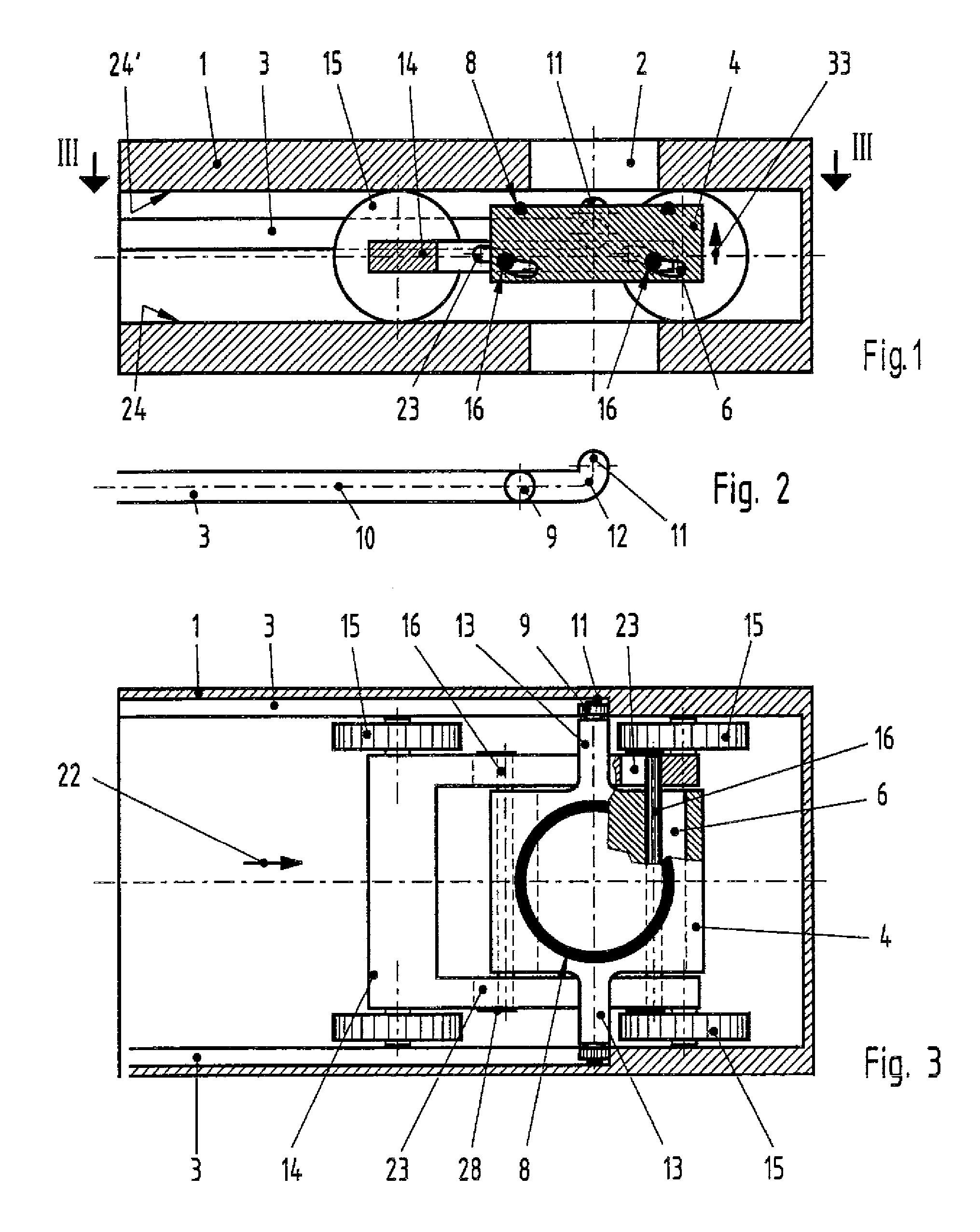
[0031]FIG. 1 is a general view of a valve mechanism of the invention in a vacuum valve, wherewith throughgoing valve opening 2 is disposed in housing 1. The valve opening can be closed off by movable valve member 4 with the aid of sealing element 8.

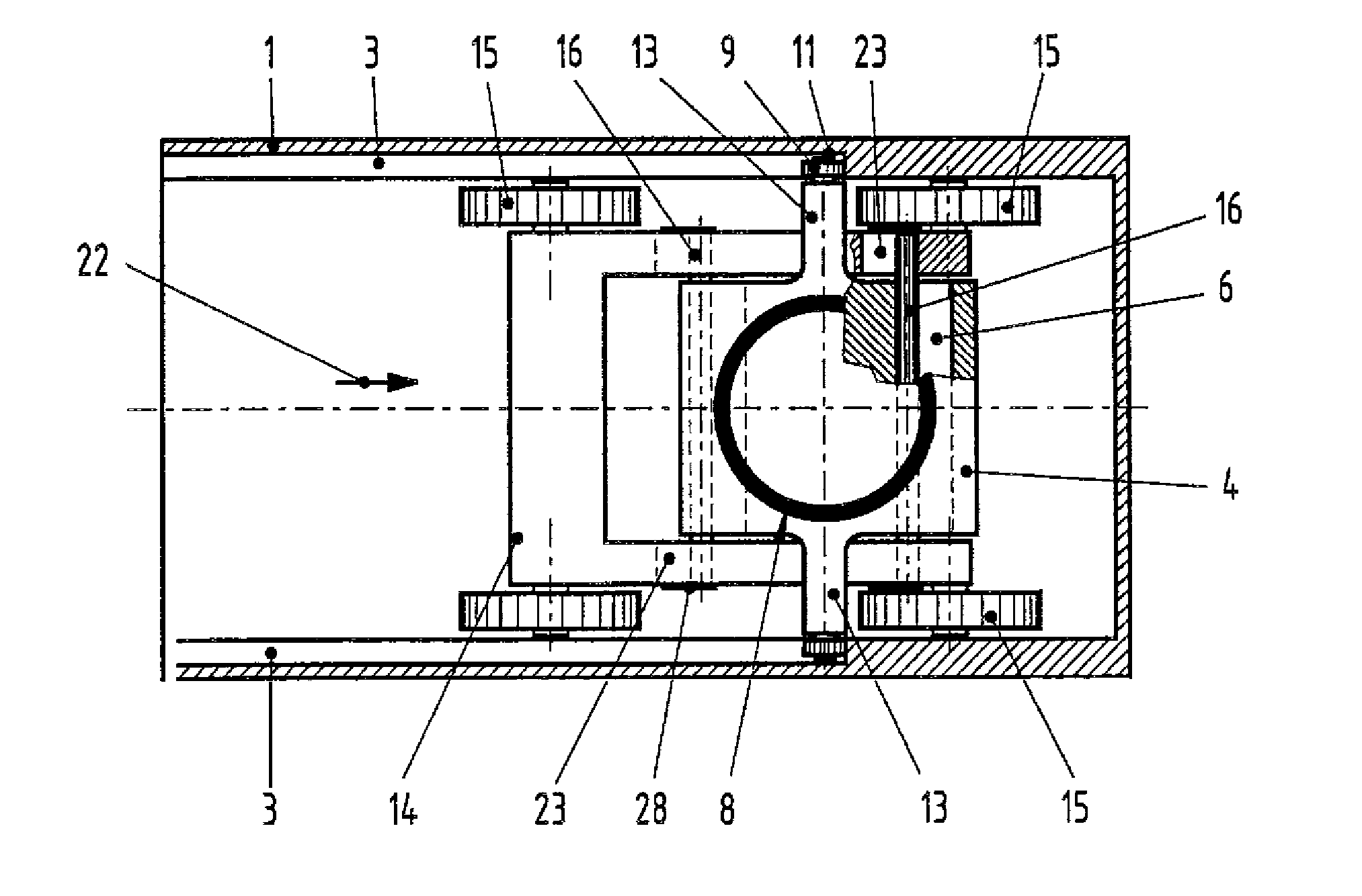
[0032]The traveling element (carriage) illustrated in FIGS. 1 and 3 is essentially comprised of drive plate 14 which is drivable back and forth in the direction of arrow 22 (see also FIG. 6);

[0033]The excursion of movable valve member 4 is effected with the aid of guideway slot 3 which is bent at its end, as shown in FIGS. 1-3, which slot 3 is formed in the two sides of the housing 1. Guideway slot 3 is engaged on both sides by rollable suspension means (wheel or roller) 9.

[0034]Guideway slot 3 and its function are illustrated more clearly in FIG. 2. Wheel 9 moves exclusively along axis 10, which axis has at its front end a part 11 which extends perpendicularly to its main direction. Between the two parts a gradual transition or radius 12...


PUM


Abstract

A valve mechanism having at least one movable valve member for sealing of a valve opening in a housing. Movements of the individual movable valve members are accomplished essentially parallelly to, and perpendicularly to, the seat surface of the valve during the opening and closing of the valve. In order to achieve high forces and low wear in the movement carried out with aid of a slot guide which guide serves to transmit forces during, and in the direction of, the opening and closing, the slot guide comprises slots which are formed in a drive plate, which slots cooperate with and overlap complementary slots in the movable valve members.

Description

FIELD OF THE INVENTION[0001]The invention relates to a valve mechanism for a vacuum valve, and more particularly to a mechanism to apply a high sealing pressure through the use of two mutually movable elements.DISCUSSION OF PRIOR ART[0002]Vacuum valves are preferred for closing of throughgoing openings in vacuum equipment. Valve mechanisms of the type described may also be used for other valves in which forced guidance is advantageous, for example, shutoff elements in pipes or the like wherein liquids are transported.[0003]A known valve mechanism is disclosed by the present Applicant in EP 0662575 B1. According to that publication, a movable valve member is rolled on fixed mounted support shafts. The costs of realizing such a solution are high, and the support shafts disclosed cannot bear as much stress as free guided roll members guided in suitable guide means without bearings.[0004]An example of bearing-free guided shafts, referred to hereinbelow as “roll bodies” in roll or cylind...

Claims


Application Information

Patent Timeline
Patent Type & Authority Patents(United States)
IPC IPC(8): F16K3/00
CPCF16K3/184F16K51/02
Inventor BOSCH, HUBERT
Owner BOSCH HUBERT
Learn More