Integrated theft deterrent device

a technology of theft deterrent device and integrated security tag, which is applied in the direction of burglar alarm mechanical actuation, lock application, instruments, etc., can solve the problems of pin bending, easy defeat of unscrupulous individuals by subjecting the tag, pin bending, etc., to reduce the risk of work place injury, and reduce labor time and costs during the attachment of the tag body to an obj

Inactive Publication Date: 2008-03-11
UNIVERSAL SURVEILLANCE CORP
View PDF9 Cites 33 Cited by
  • Summary
  • Abstract
  • Description
  • Claims
  • Application Information

AI Technical Summary

Benefits of technology

[0013]It is another objective of the invention to provide an EAS tag that is durable.
[0015]It is a further objective of the invention to provide an EAS tag that provides an integrated pin to reduce the chances of injury to persons stepping on the pin, as is commonly a problem with the pins utilized in the prior art.
[0016]It is still a further objective of the invention to provide a theft deterrent device that can be quickly and easily secured to an article made of varying materials to prevent the unauthorized removal of the article.
[0018]In keeping with the principles of the present invention, a unique EAS theft deterrent tag is disclosed wherein the pin element is integrated into the tag body via an elongated element. In integrating the pin component with the tag body, labor time and costs are reduced when removing the tag from an article being protected thereby because separate bins are not required for storing the tag body and the pin component until they are reused. In addition, labor time and costs during attachment of the tag body to an article are also reduced because the pin component is integrated therewith and a separate search for a corresponding pin is eliminated. In addition, the risk of work place injury is reduced because when the tag body falls on the floor, the pin also lays flat on the floor and should not penetrate the foot of an employee stepping thereon. Conversely, the pins illustrated in the prior art have a head on which the pin will rest and leave the shaft thereof in a vertical plane thereby increasing the risk of foot injuries.

Problems solved by technology

The hinged attachment may lead to the bending of the pin when contacting the locking component because of the predetermined arc that it must travel as a result of the hinged arrangement.
Furthermore, the hinged arrangement allows the pin to protrude vertically when the device has fallen to the floor and may lead to injury.
The riveting of the chain on the outside of the tag body may subject the tag easy defeat by unscrupulous individuals.
Furthermore, the pin thereof will protrude vertically when the device has fallen to the floor and may lead to injury.
However, the pin once again is held in a substantially hinged relation to the locking component and may lead to bending of the pin as a result of the arc which must be traveled in order to engage the locking component.
The hinged attachment may lead to the bending of the pin when contacting the locking component because of the predetermined arc that it must travel as a result of the hinged arrangement.
In addition, the hinged arrangement allows the pin to protrude vertically when the device has fallen to the floor and may lead to injury.
The Nguyen device, however, uses a traditional independent pin having a head to attach the lanyard to an article, thereby possibly leading to work place injuries when the pin is dropped on the floor.
Furthermore, the electrical components incorporated into each tag make the manufacture and use thereof cost prohibitive.
The prior art does not address the need for an integrated EAS tag that is difficult to defeat and easy to use.
In addition, the prior art fails to provide a theft deterrent tag assembly that incorporates the pin, a lanyard and the tag body into one unit.

Method used


Image

  • Integrated theft deterrent device
  • Integrated theft deterrent device
  • Integrated theft deterrent device

Examples


Embodiment Construction

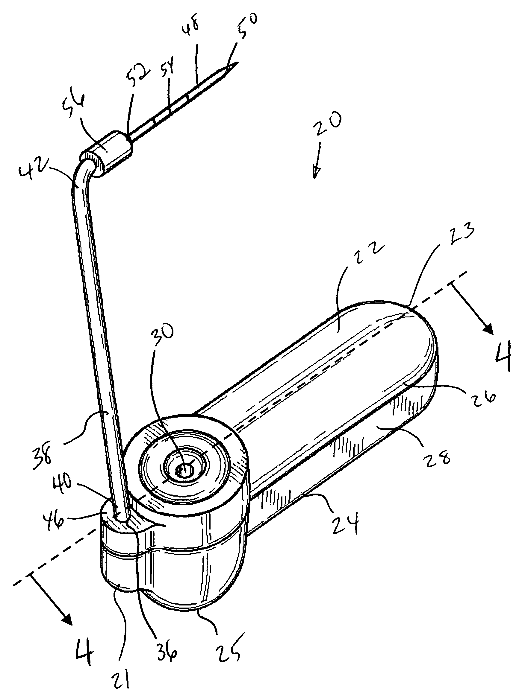
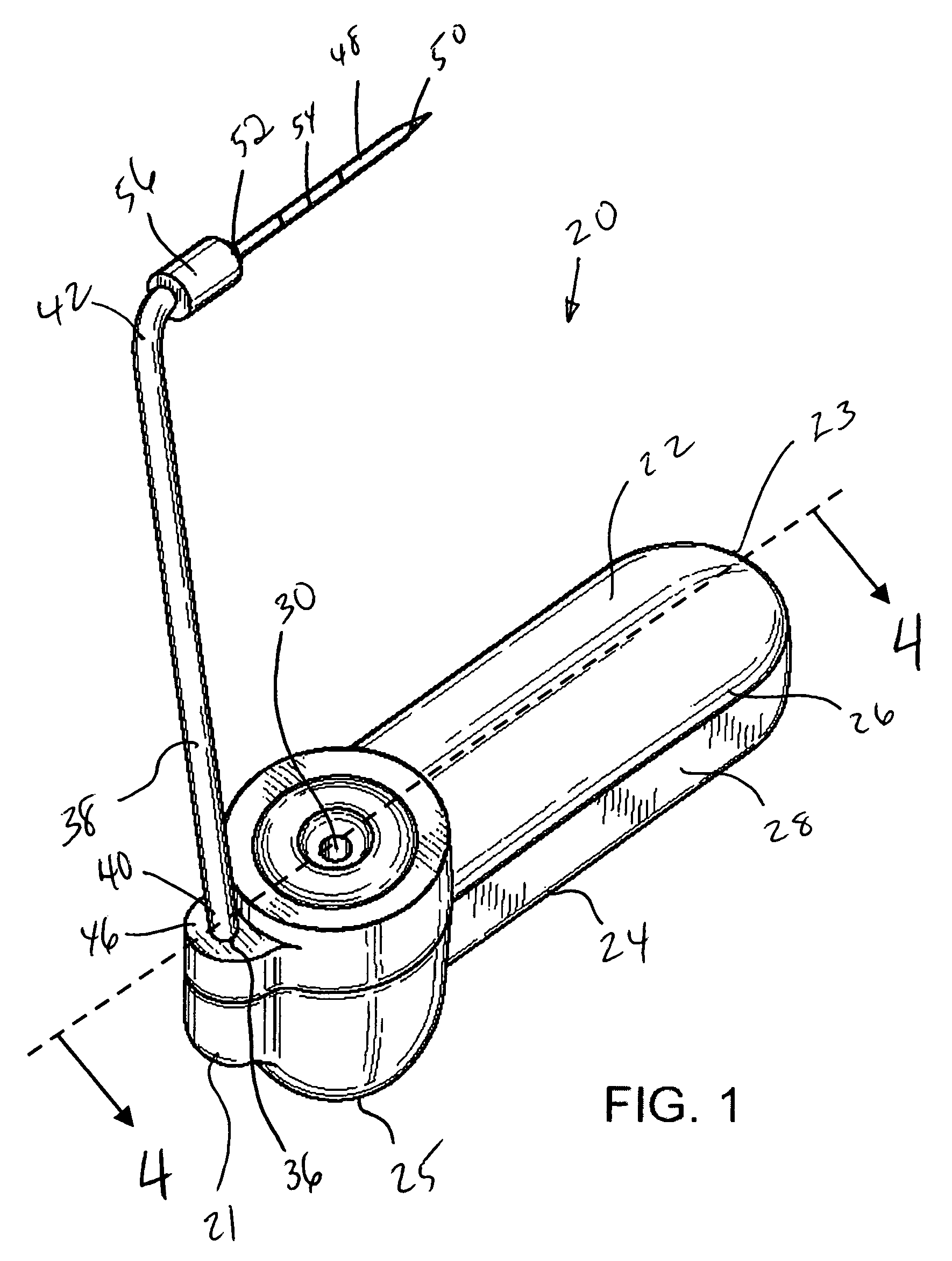
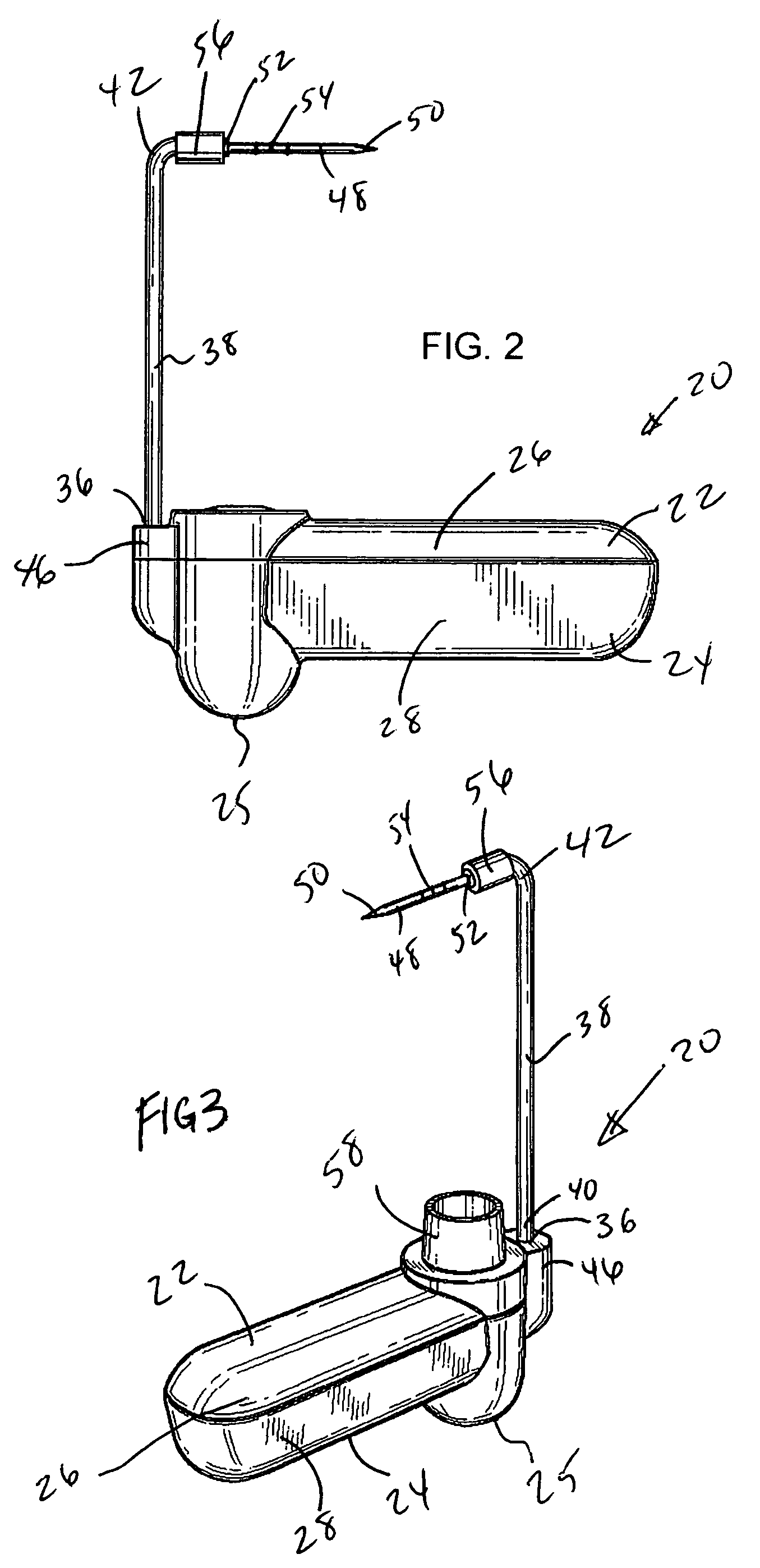
[0030]Referring now to FIGS. 1, 2 and 4, a tag 20 is illustrated having a first half 22 and a second half 24. First and second halves 22 and 24 are preferably made of a hard or rigid material and are adapted to attach to one another and form a front end 21 and a rear end 23. A usable rigid or hard material might be a hard plastic such as, for purposes of illustration but not limitation, an injection molded ABS plastic. If a plastic material is used, the mating of a first side wall 26 to a second side wall 28 can be accomplished via an ultrasonic weld or like joining mechanism. However, it is to be understood that other joining methods, such as adhesives, may also be used. When first half 22 and second half 24 are securely joined, first sidewall 26 and second sidewall 28 form a peripheral outer wall of tag 20. Second half 24 has an apex region 25 that extends therefrom in an opposing direction to first half 22 in a substantially dome shaped manner. The dome shaped apex region 25 forc...


PUM


Abstract

An integrated theft deterrent tag 20 having a lanyard 38 emanating therefrom. The lanyard 38 having a pin 48 permanently attached thereto and the pin 48 being received within a locking mechanism 32 and enclosing an article to be protected.

Description

CROSS-REFERENCE TO RELATED APPLICATIONS[0001]The contents of this application are related to U.S. design patent applications having Ser. Nos. 29 / 182,901, 29 / 182,878, and 29 / 182,914, filed on Jun. 2, 2003, the contents of which are incorporated herein by reference.FIELD OF THE INVENTION[0002]The invention relates to theft deterrent security tags in general, and in particular to an integrated security tag containing an attaching pin that emanates from the tag body for use in electronic article surveillance (EAS) tags for theft deterrence.BACKGROUND OF THE INVENTION[0003]Various types of electronic article surveillance (EAS) systems are known having the common feature of employing a marker or tag which is affixed to an article to be protected against theft from a controlled area, such as merchandise in a store. When a legitimate purchase of the article is made, the marker can either be removed from the article, or converted from an activated state to a deactivated state. Such systems e...

Claims


Application Information

Patent Timeline
Patent Type & Authority Patents(United States)
IPC IPC(8): G08B13/14E05B47/00F16B21/00E05B73/00
CPCE05B73/0017Y10T24/50Y10T24/505Y10T70/7124Y10T70/7057
Inventor SAYEGH, ADEL O.
Owner UNIVERSAL SURVEILLANCE CORP
Why Eureka
Try Eureka