Multicapacitor sensor array

a sensor array and multi-capacitor technology, applied in the field of multi-capacitor sensor arrays, can solve the problems of changing the capacitances of the two sensors, sensor arrays, etc., and achieve the effect of increasing the magnitude of peak voltag

Active Publication Date: 2008-03-18
COLLEGE PARK IND INC
View PDF9 Cites 51 Cited by
  • Summary
  • Abstract
  • Description
  • Claims
  • Application Information

AI Technical Summary

Problems solved by technology

Moreover, forces applied perpendicular to the planes of the conductor array cause the insulator to compress, thus also changing the capacitances of the two by one sets of the sensor array.

Method used


Image

  • Multicapacitor sensor array
  • Multicapacitor sensor array
  • Multicapacitor sensor array

Examples


Embodiment Construction

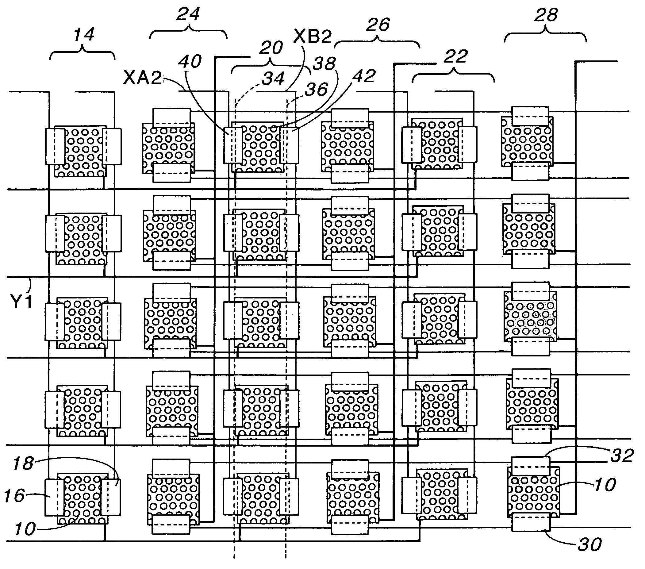
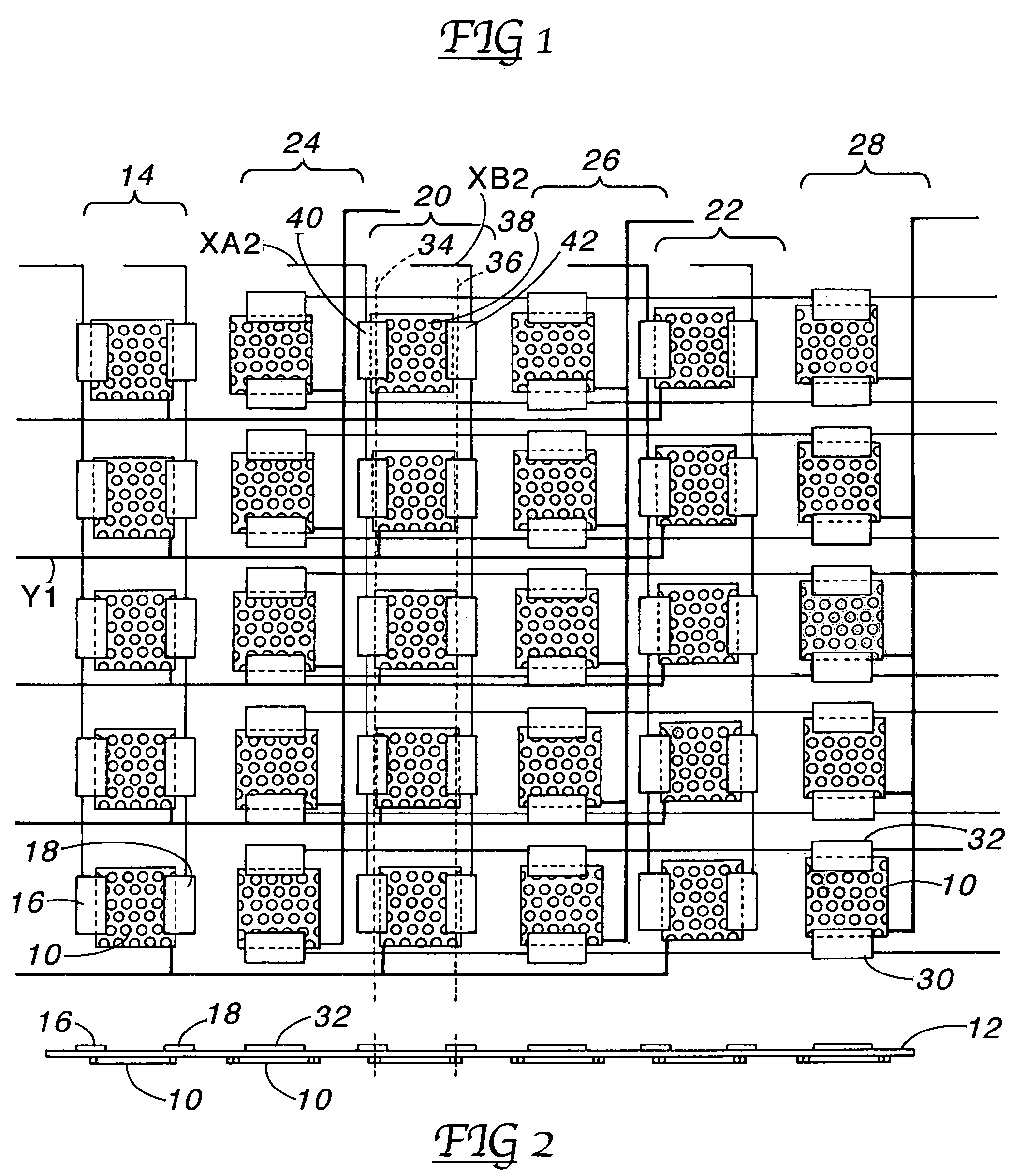
[0009]Illustrated in FIG. 1 and FIG. 2 is a sensor array comprising a plurality of square conductive drive plates 10 all lying in the same plane. Lying immediately above the drive plates 10 is a compressible flexible dielectric material 12. Atop the dielectric 12 are conductive sense plates paired above each drive plate 10. More specifically, in FIG. 1, in the first vertical row 14 the conductive sense plates 16 and 18 at the lower left corner of the array overlap the drive plate 10 to the right and left to sense shear in the horizontal X axis, as is true of the sense plates thereabove in this vertical subset row. In a similar manner, the sense plate pairs overlap the drive plates right and left in vertical subset rows 20 and 22.

[0010]In the other vertical rows 24, 26 and 28, the sense plate pairs are located top and bottom and partially overlap the drive plates, as shown at 30 and 32 to sense shear in the vertical Y axis. Thus, in alternating vertical rows, the sense plate pairs ar...


PUM

PropertyMeasurementUnit
conductiveaaaaaaaaaa
capacitanceaaaaaaaaaa
widthaaaaaaaaaa

Abstract

A new capacitive sensor array comprises a first plurality of conductors separated by a compressible insulator from a second plurality of conductors lying in a second plane parallel to the first plane. The second plurality of conductors are paired to partially overlap the first plurality of conductors, two by one in sets, whereby a shear force applied in a plane parallel to the conductor array will cause capacitance between the first and second conductors to change. Serially sampling the two by one sets for changes in capacitance provides information on both the magnitude and direction of shear. Moreover, forces applied perpendicular to the planes causes the insulator to compress, thus also changing the capacitances of the two by one sets of the sensor array. In the preferred embodiment, the imbalance of voltages between the paired conductors is applied to a differential amplifier to sense shear magnitude and direction. Compression force appears as an increase in peak voltage magnitude in both of the paired conductors.

Description

[0001]This application claims the benefit of provisional patent application No. 60 / 652,864 filed Feb. 15, 2005.BACKGROUND OF THE INVENTION[0002]The field of the invention pertains to electrical sensors for sensing axial forces and shear forces. In particular, the invention is directed to sensing shear in one or two perpendicular directions simultaneous with sensing axial force in the third direction.SUMMARY OF THE INVENTION[0003]The new sensor array comprises a first plurality of conductors separated by a compressible insulator from a second plurality of conductors lying in a second plane parallel to the first plane. The second plurality of conductors are paired to partially overlap the first plurality of conductors, two by one in sets, whereby a shear force applied to one plurality of conductors relative to the other plurality of conductors in a plane parallel to the conductor array will cause capacitance between the first and second conductors to change. Sequentially sampling the ...

Claims


Application Information

Patent Timeline
Patent Type & Authority Patents(United States)
IPC IPC(8): G01N3/24G01L1/00
CPCG01L1/146G01L5/165
Inventor HARRINGTON, RICHARD H.
Owner COLLEGE PARK IND INC
Why Eureka
Try Eureka